DYNATUNE-XL RIDE & HANDLING MODULE - WORKBOOK FEATURES
The continuous development of the DYNATUNE-XL Software Suite over the span of approximately 30 years within MS EXCEL® is an impressive feat. The DYNATUNE-XL R&H EXPERT MODULE, a culmination of this long-term development, is housed in a single workbook comprising a total of 46 different sheets. These sheets collectively contain over 6 million cells, including more than 250,000 cells with constant values. Additionally, there are several thousand conditionally formatted cells and over 500 defined calculation variables. This extensive and sophisticated structure reflects the depth and complexity of the DYNATUNE-XL R&H MODULE, making it a powerful and comprehensive tool for Vehicle Dynamics analysis.
DYNATUNE-XL DOES OFFER TWO DOCUMENTS WHICH ARE INVALUABLE TO USERS WHO ARE SEEKING TO DEEPEN THEIR KNOWLEDGE IN THE FIELD OF VEHICLE DYNAMICS:
- THE 5 "MUST KNOW" FUNDAMENTALS OF VEHICLE DYNAMICS
- THE 10 "EASY" STEPS TO HAPPY VEHICLE DYNAMICS TUNING GUIDE
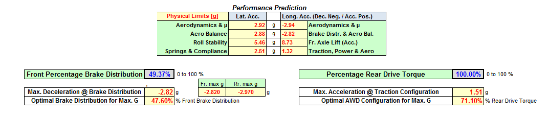
DYNATUNE-XL R&H KEY MODEL FEATURES - Physical limits PREDICTION
After each START/INITIALIZE calculation, this upfront information is updated, allowing users to iteratively refine and optimize their vehicle setups based on the predicted physical limits.
|
In both versions of DYNATUNE-XL R&H MODULE exists a specific calculation and prediction of the physical limits of the vehicle. These calculations, adapted to the complexity of the model, provide instant insights into the capabilities and "best-case" performance constraints of the vehicle.
Additionally, sophisticated tools are available within the R&H MODULE for defining optimal brake distribution to achieve maximum deceleration and determining the best front-to-rear drive torque distribution for achieving maximum longitudinal acceleration, particularly in the case of all-wheel drive (AWD) configurations. |
These features contribute to an enhanced understanding of the vehicle's performance boundaries and assist in achieving optimal handling and acceleration characteristics.
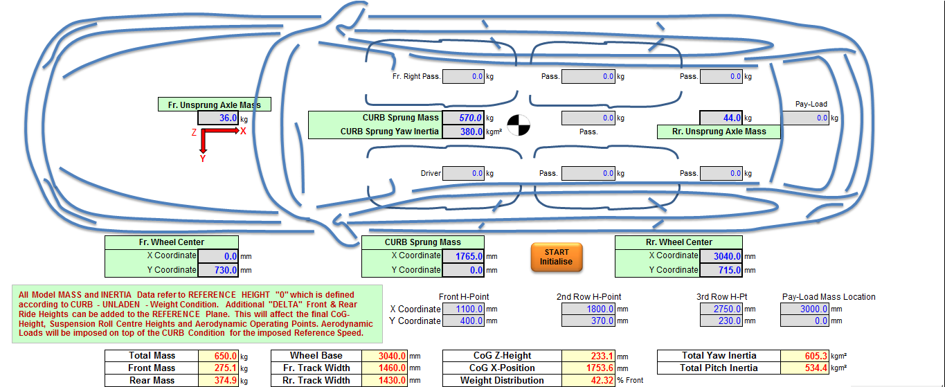
DYNATUNE-XL R&H KEY MODEL FEATURES - MASSES, INERTIA's, PASSENGERS & PAY-LOAD
|
In all versions of the DYNATUNE-XL R&H MODULE, there is a feature that allows users to add up to 8 masses, representing passengers and payload, with individual positions in the vehicle. This functionality enables users to simulate accurate Gross Vehicle Weight (GVW) conditions for various types of vehicles. In a racing environment, it also allows for the analysis of the effects of ballast weights accurately. |
|
The software automatically calculates the resulting overall Vehicle Weight, Axle Load Distribution, Vehicle Inertia, and the resulting Center of Gravity location based on the specified masses and their positions in the vehicle. This capability enhances the realism of simulations and provides a more accurate representation of the vehicle's dynamic behavior under different loading conditions.
DYNATUNE-XL R&H KEY MODEL FEATURES - POWER-TRAIN AND BRAKE-SYSTEM
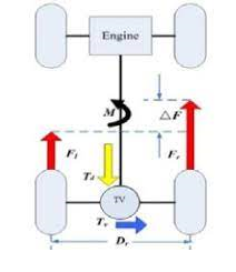
In RELEASE 8.1 of the DYNATUNE-XL R&H MODULES, enhanced features have been introduced to simulate the effects of Power-Train and Brake-System on the Handling and Stability of the vehicle. Notably, the simulation now includes the effects of Limited Slip Differentials and ideal Left/Right (L/R) Force splits, as observed in Torque Vectoring systems.These additions allow for a more comprehensive analysis of how power distribution and brake force allocation can impact the handling characteristics and stability of the vehicle. The consideration of Limited Slip Differentials and Torque Vectoring provides a much more realistic simulation, taking into account advanced technologies that influence the dynamic behavior of modern vehicles.

|
In RELEASE 8.1, users have the capability to specify for both Front and Rear Differentials whether they are open, limited slip with preload and a percentage of locking, and/or acting fully ideally by distributing traction forces optimally to each corner of the vehicle. This feature provides a detailed and customizable representation of differential behavior, allowing users to explore the effects of different configurations on vehicle dynamics.
In previous releases, it was already possible for AWD systems to distribute Fore/Aft Traction Forces either in a fixed ratio or ideally. With the updated 7-DOF Model and Tire Model in RELEASE 8.1, the simulation now incorporates the effects of resulting Yaw Moment on the vehicle and its impact on the handling balance. This is particularly relevant for investigating the effects of Torque Vectoring on vehicle dynamics. The described functionality is also applicable to Braking Forces, which can be distributed Front to Rear Ideally and/or Left to Right Ideally, providing a comprehensive analysis of how braking forces influence vehicle behavior and stability. |
|
In RELEASE 8.1, the software has been made "EV Proof," meaning that users can now activate regenerative braking in combination with hydraulic braking. This feature is designed to simulate the interaction between regenerative braking and hydraulic braking systems. It takes into account the correct suspension Anti-Angles and Brake Power Distribution into the respective Electric Vehicle (EV) Powertrain or Hydraulic Brake System.
DYNATUNE-XL R&H KEY MODEL FEATURES - AERODYNAMICS
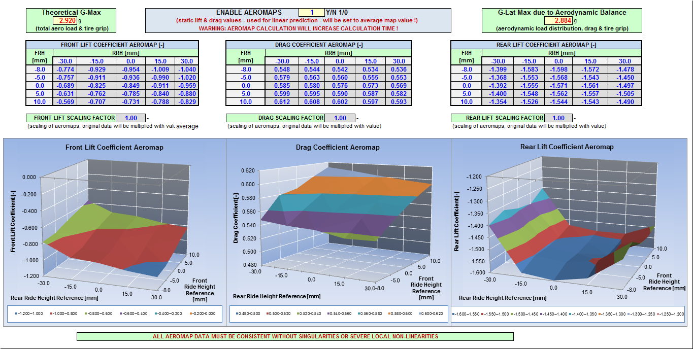
In the "RACE-" and "EXPERT" versions of the DYNATUNE-XL R&H MODULE, users have the capability to utilize sophisticated aerodynamic AEROMAPS. These AEROMAPS represent Lift and/or Drag Coefficients as a function of both front and rear ride-height. The representation includes non-linear curve-fitting, enabling correct interpolation between data points.
|
The AEROMAPS feature proves invaluable for basic race-engineering analysis of dynamics, especially in the context of wing-cars where aerodynamics play a crucial role.
Additionally, the software includes a user tool that facilitates a direct comparison between theoretically possible maximum lateral acceleration and realistically achievable lateral acceleration with the installed Aerodynamic Balance. This comparison offers insights into the practical implications of the aerodynamic setup on the vehicle's dynamic performance. |
|
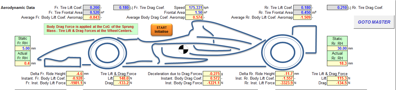
From DYNATUNE-XL RELEASE 7.1 onward, users have the additional capability to input specific values for Tire Drag and Tire Lift Coefficients. This feature is particularly useful for calculating the aerodynamics of Open Wheel Vehicles more accurately. In cases where specific data for tire coefficients is not available, these parameters can be set to zero.
|
|
Alternatively, users can work with classical one-dimensional Drag and Lift Coefficients for the entire vehicle if detailed tire-specific data is not accessible. This flexibility allows users to tailor the aerodynamic modeling to the available information and the specific characteristics of the vehicles being analyzed.
DYNATUNE-XL R&H KEY MODEL FEATURES - CHASSIS DATA
|
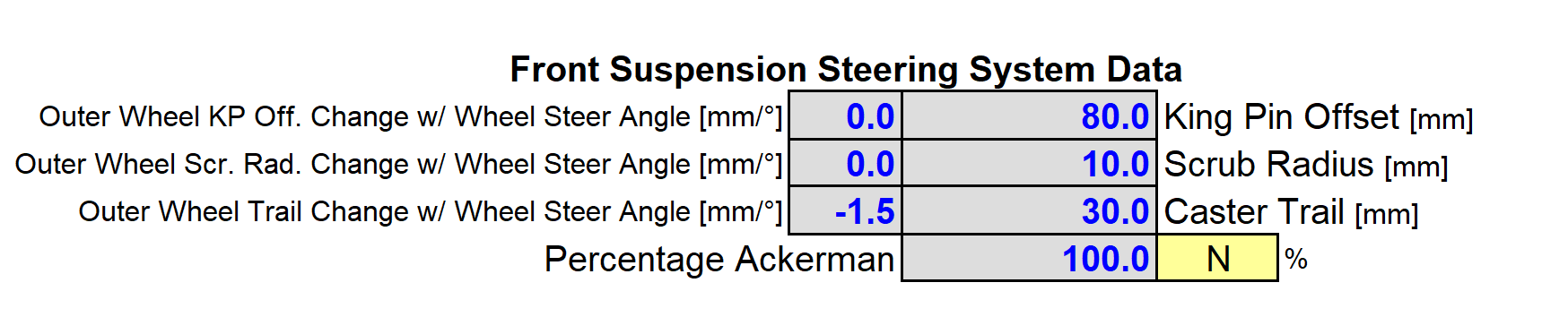
In RELEASE 8.1 of the DYNATUNE-XL R&H MODULE, a basic but accurate representation of a Steering System has been implemented. This addition allows users to analyze crucial aspects such as Steering Torque Feedback and the effects of Wheel Steer Geometry on the front Tire Slip Angles. The Steering System representation enhances the realism of simulations, providing a more comprehensive understanding of how steering dynamics impact vehicle behavior.
|
|
The inclusion of steering system characteristics further enriches the chassis data in the DYNATUNE-XL R&H MODULE, making it a more robust tool for analyzing and optimizing vehicle dynamics, especially in terms of steering response and feedback.
|
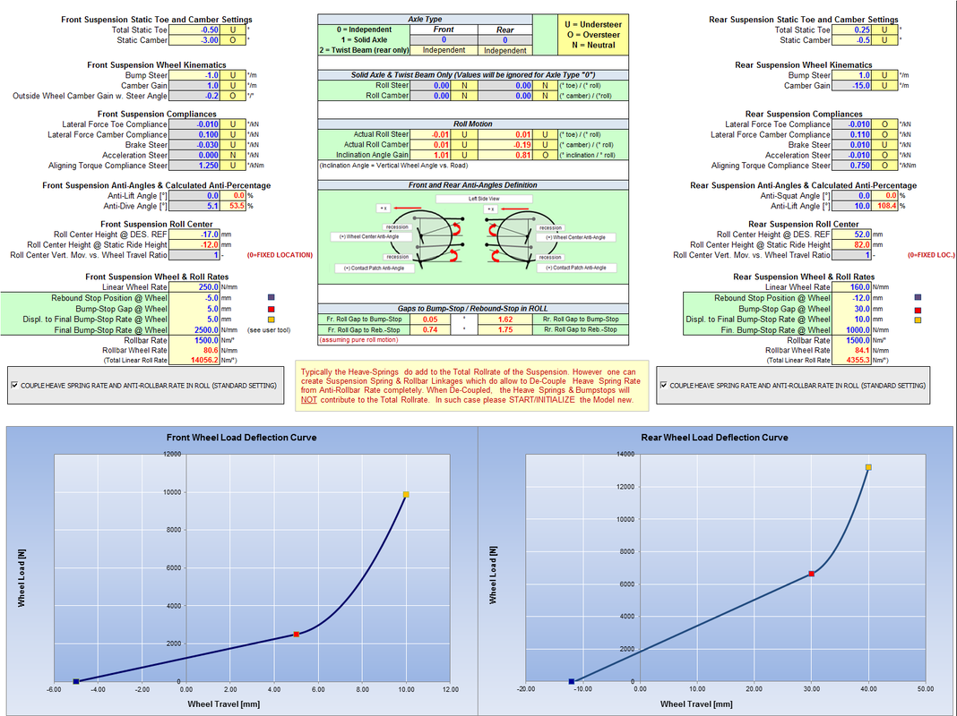
In the DYNATUNE-XL R&H MODULE, alongside the usual spring and rollbar rates, there is a dedicated section table for the most important elasto-kinematic suspension data. These parameters, well-established in the OEM Car Development world but less widely known in the Racing world, are related to commonly measured data on Kinematics and Compliance (K&C) Rigs or specific output data from Multi-Body Analysis Programs like ADAMS.
This tabular approach enables correct parametric simulation of a wide range of suspension setups, from rigid axles to mono-spring open-wheel race car configurations with de-coupled roll and ride rates. The Chassis Data Sheet also provides a Wheel Force Deflection Curve, offering a visual representation of the suspension's behavior under different loads. Additionally, users can set and parameterize Bump and Rebound Stops, providing a comprehensive toolset for detailed suspension analysis and optimization. |
Damper characteristics are handled in a unique sheet providing various levels of complexity and detailed ride analysis.
DYNATUNE-XL R&H KEY MODEL FEATURES - SUSPENSION K&C DATA USER TOOL
|
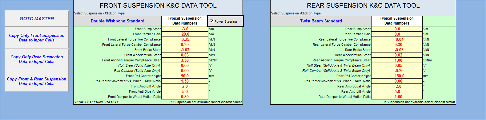
In the DYNATUNE-XL R&H MODULES, a SUSPENSION DATA TOOL has been implemented to assist users in selecting the most important Kinematics & Elastokinematic Data from a range of commonly used suspensions. This tool is particularly helpful for users who may not be experts in Kinematics and Compliance (K&C) data, providing a knowledge base to guide them in creating accurate models.
|
|
The database within the tool includes typical road suspension data as well as interesting race suspension data. An automatic data population procedure is integrated, minimizing the margin for error in the model input data. This feature streamlines the process for users, making it more accessible and reducing the likelihood of input mistakes when setting up the suspension parameters for analysis and simulation.
DYNATUNE-XL R&H KEY MODEL FEATURES - USER TOOLS
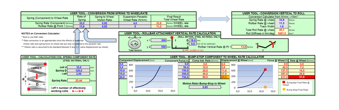
DYNATUNE-XL offers convenient User Tools in all Software Modules for simple data manipulation. These tools are particularly helpful when data in the wheel plane is not available or when detailed spring rates and anti-roll bar stiffness are not in the correct format.
These user tools are designed to assist both inexperienced users and novice race engineers in calculating correct input data for DYNATUNE-XL MODULES.
These user tools are designed to assist both inexperienced users and novice race engineers in calculating correct input data for DYNATUNE-XL MODULES.
Over many years of application, these USER Tools have proven to be appreciated by experienced users as well, providing a quick and efficient way to change between various data formats. This flexibility makes all DYNATUNE-XL MODULES more accessible and user-friendly, streamlining the process of preparing and inputting data for analysis and simulation.
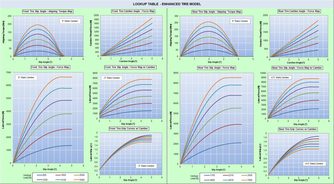
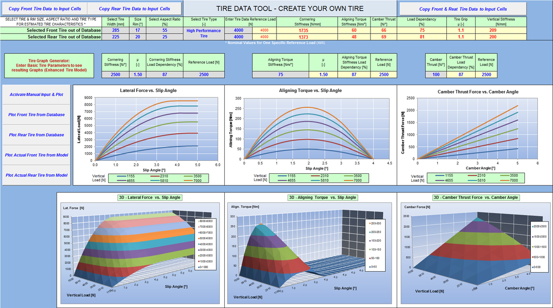
DYNATUNE-XL R&H KEY MODEL FEATURES - TIRE DATA
|
In RELEASE 8.0 and onward, all Tire Data for both the BASE TIRE model and the ENHANCED TIRE Model are consolidated in the TIRE DATA worksheet. This centralization enhances user convenience by providing a single location for all relevant tire data. Additionally, for user-friendly interpretation, graphs are available to plot various tire parameters, facilitating a quicker understanding of the effects of each parameter on tire behavior.
In RELEASE 8.0, two notable features have been introduced. First, Tire Grip can now be made load-dependent, allowing for a more realistic representation of tire performance under varying loads. Second, the Camber Thrust force is factored into the total lateral grip/friction coefficient calculation. These features contribute to a more refined representation of tire and car performance in the 7-DOF Vehicle Model, offering a more accurate simulation of the dynamic interaction between the vehicle and the tires. |
|
DYNATUNE-XL R&H KEY MODEL FEATURES - TIRE DATA USER TOOL
|
All DYNATUNE-XL R&H MODULES come with an Empirical Tire Data-Base that includes exemplary parameters based on tire dimensions for the BASE TIRE Model. This tool not only provides the convenience of using a knowledge base but also allows users to plot all the tire parameters in a typical tire data representation graph as shown on the left.
In addition to utilizing the provided tire data, the tool offers the capability to create a custom tire set in a straightforward manner. Automatic routines are available to populate the data into the model, minimizing the margin for error during the input process. |
All Tire Data is presented in 3D Carpet Plots, enhancing the visualization of tire characteristics and facilitating a more comprehensive understanding of how different parameters impact tire behavior in the context of vehicle dynamics.
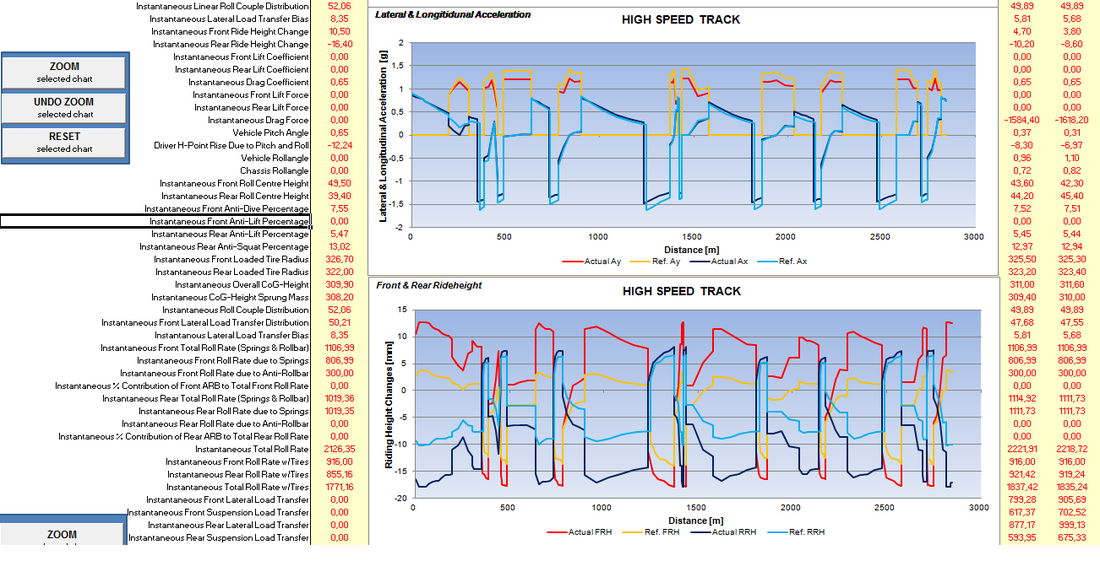
DYNATUNE-XL R&H KEY MODEL FEATURES - 7 DOF VEHICLE MODEL RESULTS
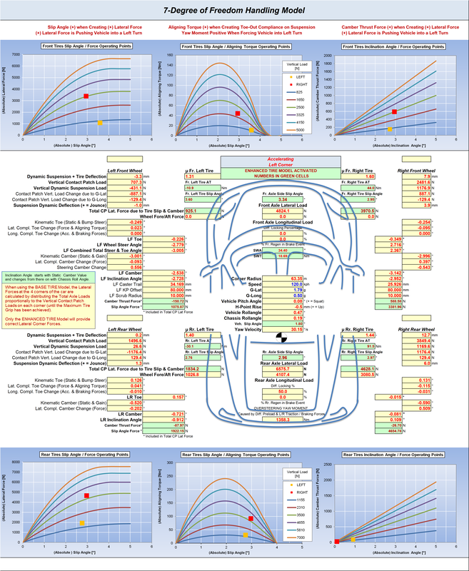
As demonstrated above, the 7-DOF Vehicle Model in the DYNATUNE-XL R&H MODULE provides comprehensive vehicle results, including Corner Loads, Suspension Loads, Tire Loads, and Instantaneous Wheel Alignment/Steer Values. This information is presented together for a holistic view, and more details can be explored on the Model Website Page.
In RELEASE 8.0, specific tire information such as Tire Operation Points, Tire Slip Angles, and other relevant data is presented either in graphs or dedicated green cells (for the ENHANCED TIRE Model). This feature allows users to gain a more detailed understanding of what is happening at each corner of the car, enhancing the analysis of tire behavior.
Furthermore, in RELEASE 8.1, all relevant results for the new Steering System, Limited Slip Differentials, and Yaw Moment have been added, providing an even more comprehensive and detailed representation of the vehicle's dynamic behavior.
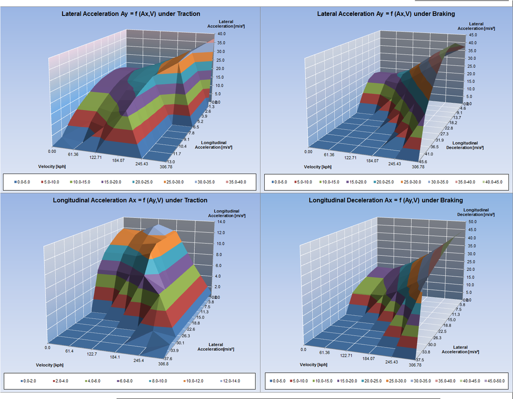
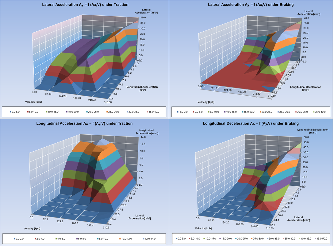
DYNATUNE R&H KEY MODEL FEATURES - PERFORMANCE ENVELOPE CALCULATION
In both the "RACE-" and "EXPERT" versions of the DYNATUNE-XL R&H MODULE, there is a unique feature that allows the calculation of the PERFORMANCE ENVELOPE, specifically for combined Lateral and Longitudinal Acceleration at various velocities. This feature is designed to provide a comprehensive understanding of the vehicle's lateral performance capabilities under different driving conditions, including traction and braking.
The results are presented in 3-Dimensional Carpet Plots, offering a convenient visualization of (combined) lateral & longitudinal performance capabilities. These plots help "at the glance of an eye" to identify areas where the vehicle might experience deficiencies, guiding engineers and users in optimizing the vehicle's dynamic behavior in that area.
Moreover, users can set a limit to the Understeer Gradient and Vehicle Side Slip Angle Gradient, allowing subjective perceptions of Understeer and Oversteer from the driver to be considered in defining the performance limits of the vehicle.
The calculation of the PERFORMANCE ENVELOPE can be executed with both LINEAR and NON-LINEAR methods. The LINEAR calculation predicts the limit by linear prediction/extrapolation, while the NON-LINEAR iterative calculation provides a more accurate result, albeit at the cost of increased computation time due to the number of iterations needed to find the physical limits.
These PERFORMANCE ENVELOPES serve as THE Foundation for LAPTIME SIMULATION, helping to determine the optimal operating points for Longitudinal and Lateral Acceleration at every point on the track.
In RELEASE 8.1 of the DYNATUNE-XL R&H MODULES, all effects of non-equal left/right longitudinal force split are considered in the total performance evaluation of the car. The impact of brake system limitations, such as restricting brake forces to be equal on the left and right sides, is evident in the pictures below. The limitation significantly constrains the performance envelope.
However, by allowing a 50% Traction Limited Slip Differential (LSD), the vehicle performance in traction approaches that of full ideal torque vectoring performance. This feature enables users to assess the influence of differential characteristics on the overall performance of the vehicle, providing insights into how different setups affect traction and vehicle dynamics.
However, by allowing a 50% Traction Limited Slip Differential (LSD), the vehicle performance in traction approaches that of full ideal torque vectoring performance. This feature enables users to assess the influence of differential characteristics on the overall performance of the vehicle, providing insights into how different setups affect traction and vehicle dynamics.
Ideal L/R Braking & Traction (FULL Torque Vectoring)
|
Rear 50% LSD and NO Ideal
L/R Braking
|
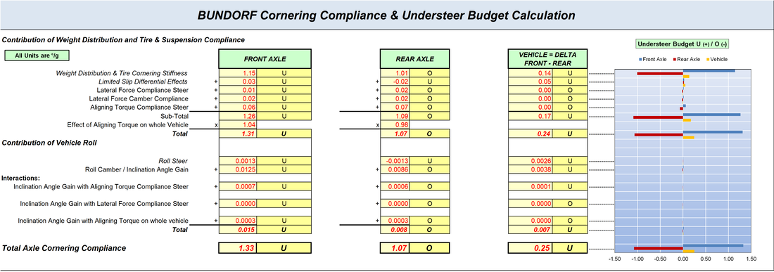
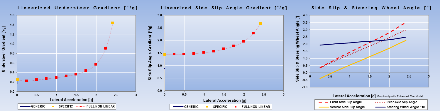
DYNATUNE-XL R&H KEY MODEL FEATURES - UNDERSTEER BUDGET CALCULATION
|
The backbone of the DYNATUNE-XL R&H MODULE is the Bicycle Model, a foundational concept in vehicle dynamics.
Historically, Tom Bundorf (SAE Technical Paper 760713, 1976) introduced a method to incorporate the effects of Suspension Kinematics & Compliances and Roll Effects onto this 2 Wheel Model. This approach demonstrated remarkable correlation with real-world data. |
|
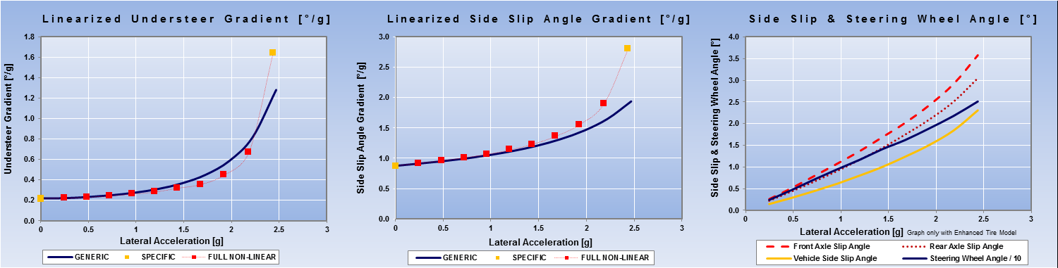
The "BUNDORF" Method defines the "Linear Understeer Gradient," a powerful and crucial metric in vehicle dynamics. The Linear Understeer Gradient is a key indicator that describes both vehicle stability and vehicle balance. It plays a pivotal role in characterizing the dynamic behavior of a vehicle. In essence, an accurate representation of the Linear Understeer Gradient is essential for capturing the nuanced and balanced performance of a vehicle in different driving conditions. A correct Understeer Gradient is fundamental for ensuring the accuracy and reliability of vehicle dynamics simulations and analyses.
In RELEASE 8.1 The Effects of Limited Slip Differential(s) & Yaw Moment have been included in the BUNDORF Understeer Buget Calculation.
DYNATUNE-XL R&H KEY MODEL FEATURE
UNDERSTEER GRADIENT & SIDE SLIP ANGLE GRADIENT ENVELOPES
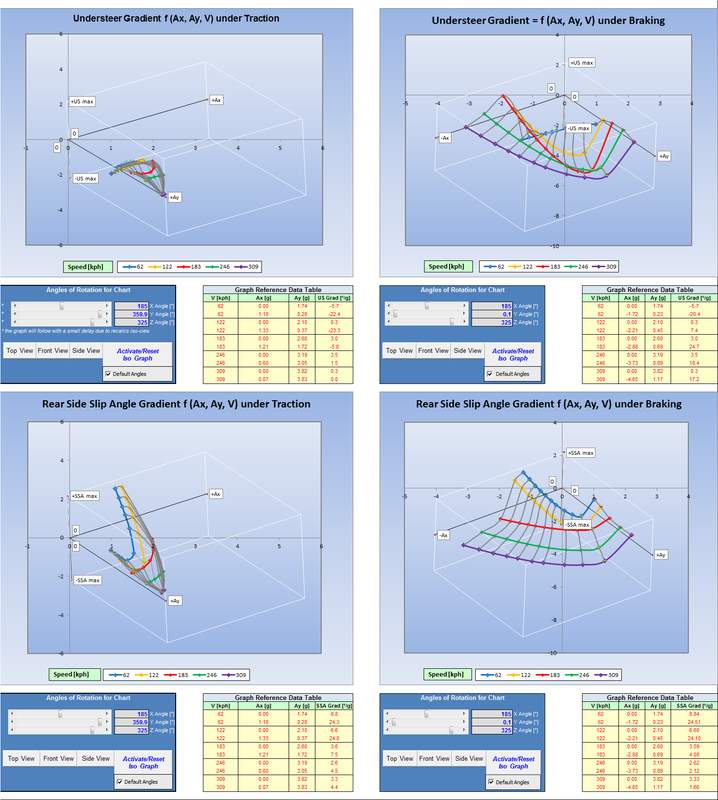
The combination of the "PERFORMANCE ENVELOPE PROCEDURE" and the "BUNDORF" UNDERSTEER BUDGET PROCEDURE" for each data point of the envelope leads to a unique 3.5D Graphic Presentation of the Understeer Gradient (UG) and the Rear Axle Side Slip Angle Gradient (SSAG).
Utilizing advanced iso-metric projection algorithms allows the creation and projection of a response surface for UG/SSA Gradient as a function of Lateral Acceleration, Longitudinal Acceleration, and Velocity. This graphical representation provides a comprehensive view of the entire operating range of vehicle balance in a few unique sets of graphs. It enables the identification & correlation of Driver Comments with respect to any problematic areas of the car immediately, offering as such an immensely powerful and effective tool for expert analysis and race engineer / driver communication.
The procedure can be applied in both LINEAR and NON-LINEAR modes, and it includes four pre-defined custom graphs covering all combined braking/acceleration and lateral acceleration situations. Each custom graph offers the flexibility to explore the surface plot from various angles, and users can manually set specific viewing angles for each view if desired. This feature enhances the ability to conduct detailed and nuanced analyses of the vehicle's dynamic behavior.
DYNATUNE-XL R&H KEY MODEL FEATURES - STANDARD OBJECTIVE HANDLING MANEUVERS
The DYNATUNE-XL R&H MODULES provide a variety of standard handling maneuvers in all versions. In addition to typical graphs for each handling maneuver, the software offers a range of commonly used vehicle dynamics metrics. These metrics serve as key performance indexes (KPI) and are often used to track program development advancements or act as reference parameters for upfront bench marking. The inclusion of such metrics enhances the analytical capabilities of the software and allows users to assess and optimize vehicle performance across various handling scenarios.
Constant Velocity LATERAL SWEEP
|
CONSTANT RADIUS LATERAL SWEEP
|
|
|
|
In the CONSTANT VELOCITY LATERAL SWEEP, the vehicle performs a quasi-static lateral acceleration sweep at a constant velocity. This means that the radius of curvature tightens up with increasing lateral acceleration. This procedure is applied when one is interested in examining the vehicle balance and maximum lateral performance at a given speed. It allows for a detailed analysis of how the vehicle behaves in terms of lateral dynamics as the lateral acceleration increases while maintaining a constant velocity.
This maneuver is valuable for understanding the handling characteristics and limits of the vehicle under different lateral acceleration conditions. |
In the CONSTANT RADIUS LATERAL SWEEP, the vehicle performs a quasi-static combined lateral acceleration and velocity sweep in order to maintain a constant radius of curvature. This procedure is applied when one is interested in examining the vehicle balance and maximum lateral performance at a fixed curvature. It allows for a detailed analysis of how the vehicle behaves in terms of lateral dynamics as both lateral acceleration and velocity vary to maintain a constant curvature.
This maneuver is valuable for understanding the handling characteristics and limits of the vehicle under different combined lateral acceleration and velocity conditions while keeping the turning radius constant. |
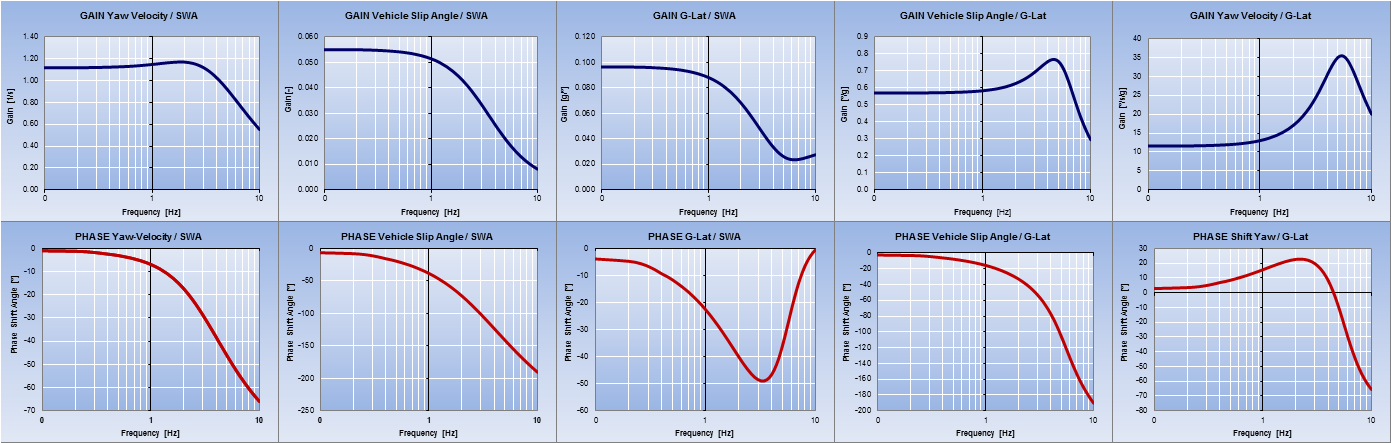
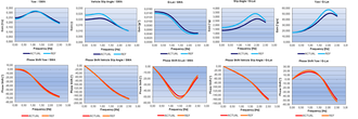
FREQUENCY STEER TEST
|
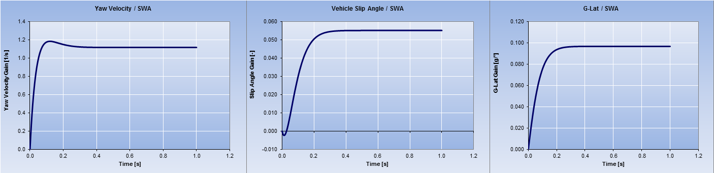
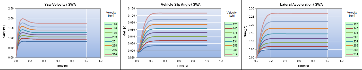
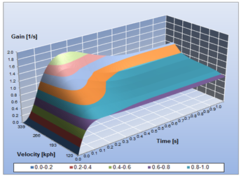
STEP STEER TEST
|
|
|
|
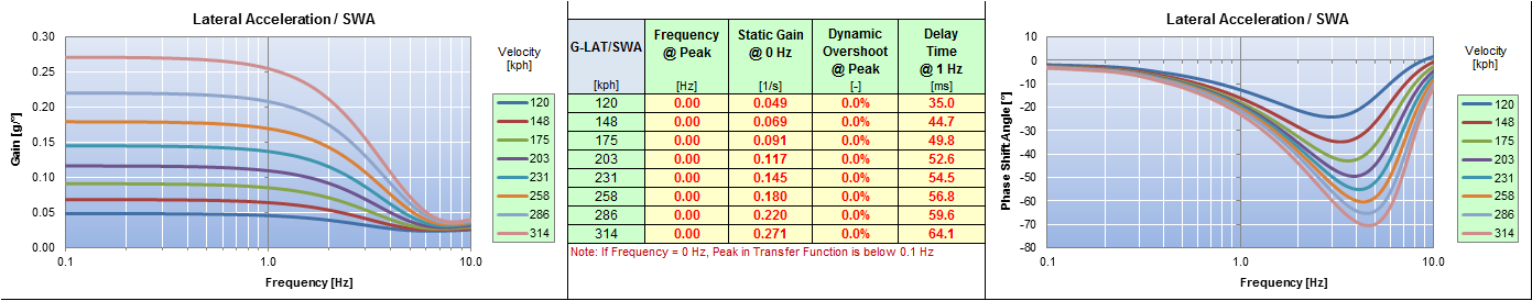
The Frequency Steer Response Test is calculated with the Linear Bicycle Model, providing in the frequency domain the transfer functions for Yaw Gain, Slip Angle, and Lateral Acceleration.
This test can be executed generically or as a function of specific steering wheel angle input, which is particularly helpful for model correlation to measured data. Various commonly used key metrics are available, and in RELEASE 8.0, the procedure has been refined by providing automatic calculation procedures covering the complete speed range of the vehicle. This refinement enhances the efficiency and accuracy of the frequency steer response analysis in capturing the dynamic behavior of the vehicle. |
The Step Steer Response is based on the Linear Bicycle Model, providing typical generic time domain responses for Yaw Gain, Slip Angle, and Lateral Acceleration. Various commonly used reference key metrics are offered in all program versions.
By providing a specific steering wheel angle, a real-life test event can be simulated and tuned to achieve a particular final lateral acceleration. In RELEASE 8.0, the procedure has been refined by adding automatic calculation to cover the whole speed range of the vehicle. This enhancement improves the accuracy and versatility of the step steer response analysis, allowing for a more comprehensive understanding of the vehicle's dynamic response. |

|
|
DYNATUNE-XL R&H KEY FEATURES - RESULTS SHEET & DATA COMPARISON
Both the "RACE-" and "EXPERT" versions of the DYNATUNE-XL R&H MODULE include a freely customizable RESULTS Sheet. This sheet comes standard with all input and output data of the current vehicle model, providing the possibility of setting your actual data set as a reference data set or reloading a reference data set to your actual data set.
All data are stored in columns, allowing for quick database manipulation, graph generation, comparison, and eventual custom post-processing. This customizable RESULTS Sheet enhances the user's ability to manage, analyze, and compare data efficiently, supporting a more comprehensive evaluation of the vehicle's performance across different scenarios or configurations.
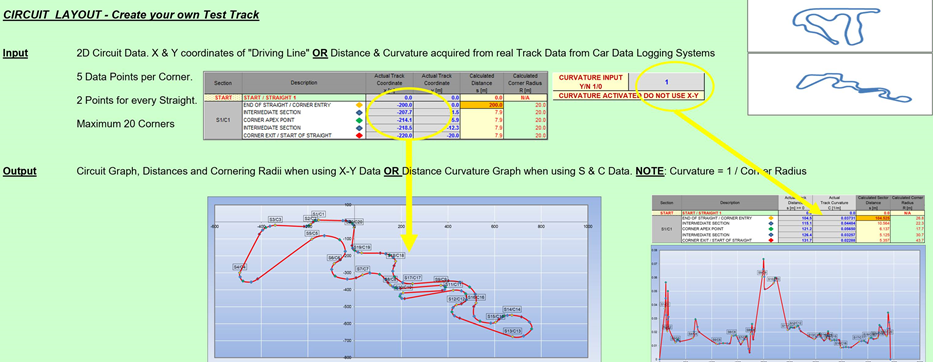
DYNATUNE-XL R&H KEY MODEL FEATURES - TEST-Track/CIRCUIT LAYOUT TOOL
|
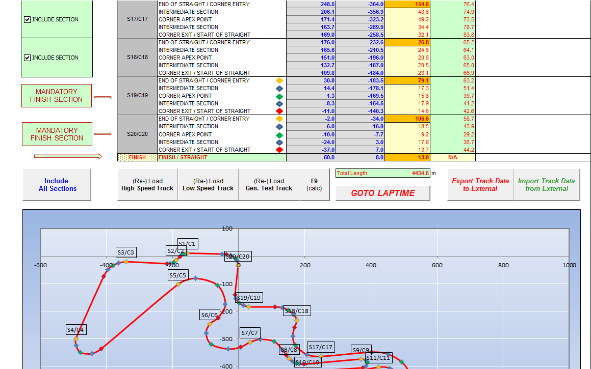
In the DYNATUNE-XL "RACE-" and "EXPERT" Versions, a convenient Test-Track & Circuit Layout tool allows for easy creation of a Test-Track, Circuit, or Rally Stage. Starting from a minimum of 4 corners and a start & finish straight, the user can create a track with up to a total of 20 corners. Each corner is defined by 5 points: Corner Entry, Intermediate Entry Point, Corner Apex, Intermediate Exit Point, and Corner Exit Point. Straights are defined by Corner Exit and the next Corner Entry Point. All these points must reflect the driving line on the Test-Track/Circuit.
Based on the 5 corner points, the corresponding corner radii will be calculated. If the track does not follow the ideal driving line (rule of diminishing radius on entry & increasing radius on corner exit), error flags will be shown, identifying where the data needs to be corrected. This tool assists users in accurately modeling and analyzing vehicle dynamics on different tracks or circuits. |
|
|
As an alternative to the visually more appealing X-Y Track Coordinates Map, it is also possible to represent track data in the commonly used Distance-Curvature Format, as shown in the left picture. This format is readily provided by most on-car data logging systems, which calculate the curvature (equal to 1/Radius) from measured lateral acceleration and velocity. |
This approach allows for the creation of fundamental input data for track geometry in the system, and it enables the easy creation of a reference database for all relevant tracks without the need for detailed mapping. This feature enhances the flexibility and efficiency of the tool, accommodating different formats commonly used in track data representation.
The Track Layout Feature comes with 3 complementary Test-Tracks, a typical High Speed Handling Track, a typical Low Speed Handling Track and an example of a short Generic Test-Track with 6 constant radius corners. At this point it should be mentioned that the DYNATUNE-XL R&H MODULE has not been focused on being a Laptime Simulation Tool Only. It is far more a Tool for a complete Vehicle Dynamics Analysis providing on top of that also a Laptime Simulation Tool.
DYNATUNE-XL R&H KEY MODEL FEATURES - LAPTIMe SIMULATOR
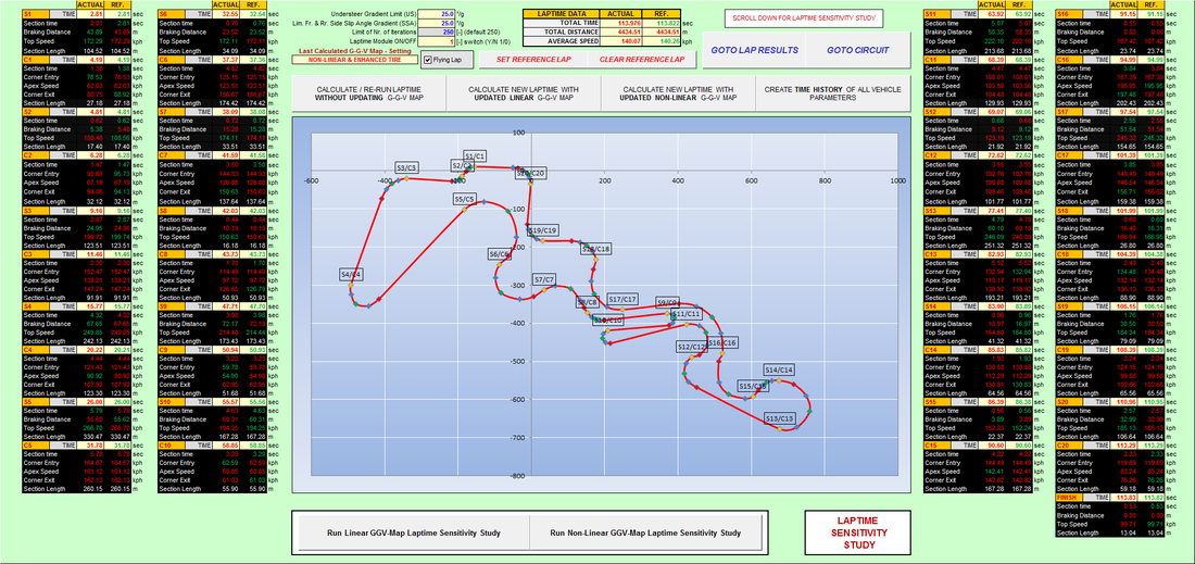
In addition to the Bicycle and 7-DOF Vehicle Models, a major feature in both DYNATUNE-XL R&H MODULES is the quasi-static 2-Dimensional LAPTIME SIMULATOR (without consideration of any inertial or transient damping effects).
Using the PERFORMANCE ENVELOPES as a reference for vehicle performance, an optimization algorithm minimizes the time needed to drive a lap on a given circuit by finding the best compromise between lateral and longitudinal acceleration in each corner and the best braking point on each straight. Logic decision functions monitor and, if necessary, control whether any modifications need to be made to these algorithms. The CONTROL PANEL shows the most important data in a typical "time table" format, such as section times, top speeds, and braking points for both the actual vehicle setup and a reference setup.
LAPTIME SIMULATION can be performed based on either a LINEAR PERFORMANCE ENVELOPE or a NON-LINEAR PERFORMANCE ENVELOPE (with consequent increased simulation times). Additionally, the tool provides the possibility of creating a time history data set of a simulated lap, including all DYNATUNE-XL R&H MODULE parameters, for more detailed, in-depth analysis of each distance point of that lap.
If desired, one can execute a TIME HISTORY calculation of a simulated lap, creating corresponding vehicle data for each data point on the track. The results of this procedure are presented in the "LAP RESULTS" sheet.
DYNATUNE-XL R&H KEY MODEL FEATURES - LAP TIMe SENSITIVITY STUDY
|
With RELEASE 8.0 of the DYNATUNE-XL R&H MODULE a new and convenient "Laptime Sensitivity Study" has been introduced, enabling the user to run a study on which of the typical track-side tuning parameters provides the most gain in lap time for the selected track.
The user can set the amount of change for each parameter, and the results of those changes are presented with absolute and relative lap time differences. All runs can be plotted on top of each other, if desired, to check where the main differences are. This feature provides valuable insights into the impact of various tuning parameters on overall lap time. |
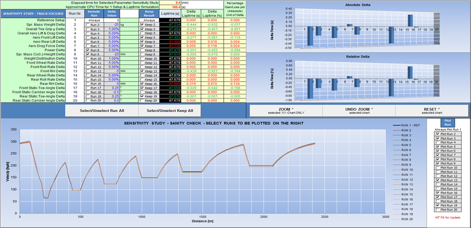
Up to 20 parameters can be selected and calculated automatically.
|
DYNATUNE-XL R&H KEY MODEL FEATURES - LAP RESULTS COMPARISON FEATURE
In the "RACE-" & "EXPERT" versions of DYNATUNE-XL R&H MODULE, the LAP RESULTS Sheet allows for a quick comparison of detailed time history data of a Reference Lap in comparison to the current Actual Lap. This LAP RESULTS Sheet contains all important metrics and is fully customizable, similar to the RESULTS sheet of the Objective Test Procedures.
A "Dynamic Zoom" feature permits mouse-zooming directly into the graphs, making closer looks and detailed comparisons very quick and efficient. Furthermore, the time history data of the Reference Lap can be exported to an external file for eventual custom post-processing or other in-house use.
A "Dynamic Zoom" feature permits mouse-zooming directly into the graphs, making closer looks and detailed comparisons very quick and efficient. Furthermore, the time history data of the Reference Lap can be exported to an external file for eventual custom post-processing or other in-house use.
DYNATUNE-XL R&H KEY FEATURES - SPRING & DAMPER RIDE TUNING
PERCENTAGE CRITICAL DAMPING
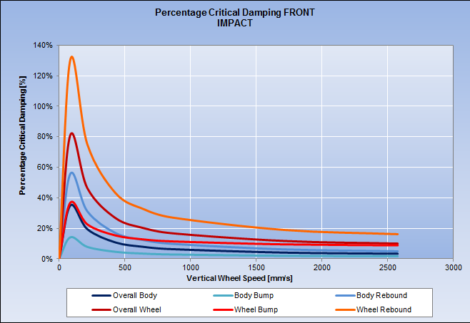
In both "RACE-" and "EXPERT" versions of the DYNATUNE-XL R&H MODULE, Percentage Critical Damping charts are available for both "Compression" and "Rebound" as well as for Damper Velocities. Plots are provided for both body and wheel damping in continuous movement events or impact-like events. These charts offer a classic presentation of Percentage Critical Damping values, providing insights into the damping characteristics of the vehicle.
|
Front vs. Rear wheel rate carpet plots
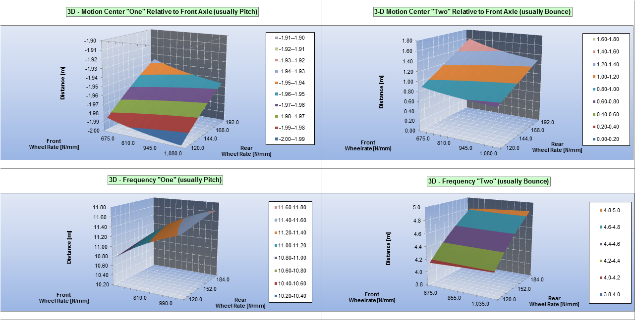
The DYNATUNE-XL R&H MODULES feature Bounce & Pitch Center Carpet Plots that depict the relationship between Front and Rear Wheel Rates and their combined effect on Bounce & Pitch Center Locations. These carpet plots provide a unique graphic representation, offering insights into how variations in wheel rates impact the vehicle's bounce and pitch characteristics.
|
DYNATUNE-XL R&H KEY FEATURES - RIDE TUNING DYNAMIC MANEUVERS
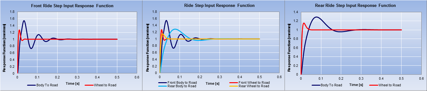
RIDE STEP RESPONSE FUNCTION
|
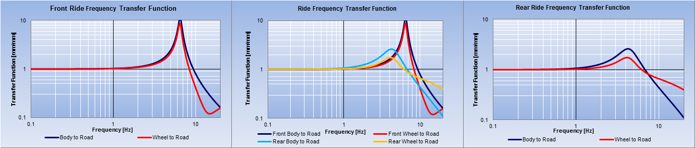
RIDE FREQUENCY TRANSFER FUNCTION
|