DYNATUNE SUSPENSION DESIGN MODULE - WORKBOOK FEATURES
The DYNATUNE-XL SUSPENSION DESIGN MODULE was originally developed in 1989 using FORTRAN and later rewritten in Turbo Pascal. Until 2007, the software's calculation algorithm couldn't be integrated into MS EXCEL ® due to the absence of standard MATRIX functions, which only became available in MS EXCEL/OFFICE 2007 ®. Presently, the workbook exists in its most intricate form, comprising 26 worksheets. When populated with results, it encompasses over 17 million cells, constructed with more than 22,000 formula calculation cells.
DYNATUNE-XL DOES OFFER TWO DOCUMENTS WHICH ARE INVALUABLE TO USERS WHO ARE SEEKING TO DEEPEN THEIR KNOWLEDGE IN THE FIELD OF SUSPENSION DESIGN:
- THE 5 "MUST KNOW" FUNDAMENTALS OF VEHICLE SUSPENSION DESIGN
- THE 10 "EASY" STEPS TO HAPPY (ELASTO-) KINEMATICS DESIGN GUIDE
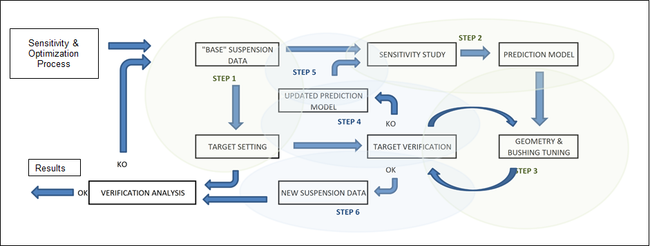
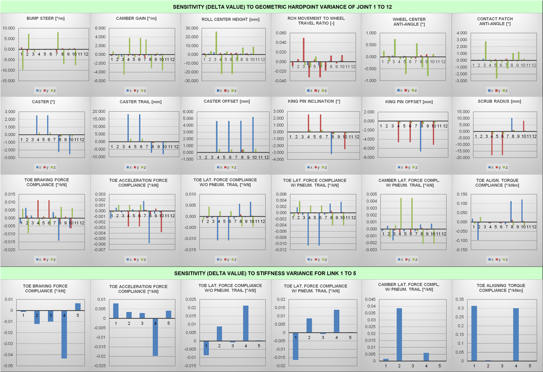
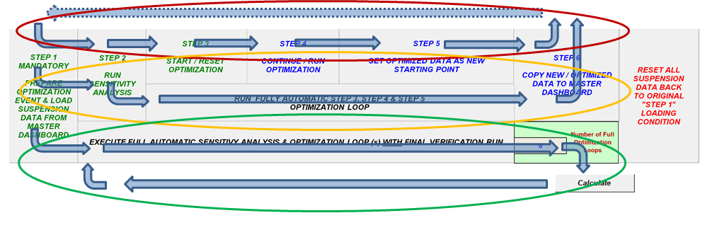
In RELEASE 8.1 of the SUSPENSION DESIGN MODULE, DYNATUNE-XL has introduced a truly unique optimizer for kinematic and elasto-kinematic suspension characteristics in the "Expert" Version. This innovative tool empowers users to create the optimal suspension geometry and most suitable link stiffness (bushing) values in a quasi full-automatic mode, accomplishing this task within a matter of minutes. The optimization method is grounded in the principle of a Linear Sensitivity/Screening Design of Experiments (DOE), as illustrated in the optimization process outlined below.
DYNATUNE SUSPENSION DESIGN MODULE - USER INTERFACE - OPTIMIZER INPUT DATA
Before delving into the comprehensive details of the DYNATUNE-XL SUSPENSION DESIGN MODULE features, here's a brief overview of the interface of the Elasto-Kinematic Optimization feature, highlighting the most important information.
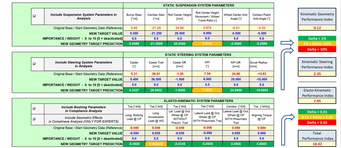
Utilizing a "Sensitivity Study" for each X-, Y-, & Z-Coordinate and Link-Stiffness in the Suspension System, the Optimization Procedure is designed to minimize the difference between actual performance and target performance. This is achieved by means of a proprietary DYNATUNE-XL Cost Function, presented to the Users as the "Suspension Performance Index".
|
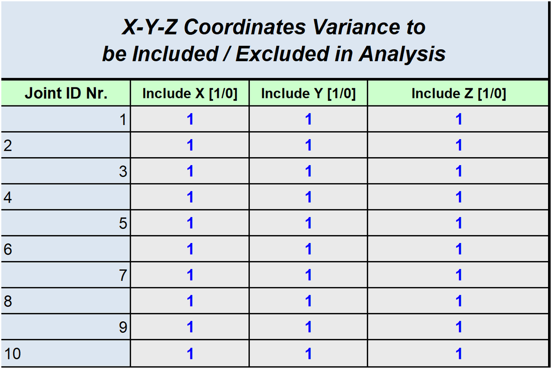
The user has complete control over the constraints for the optimization exercise. Each coordinate of the suspension link joints can be activated or deactivated on request, allowing consideration of important packaging constraints, for example.
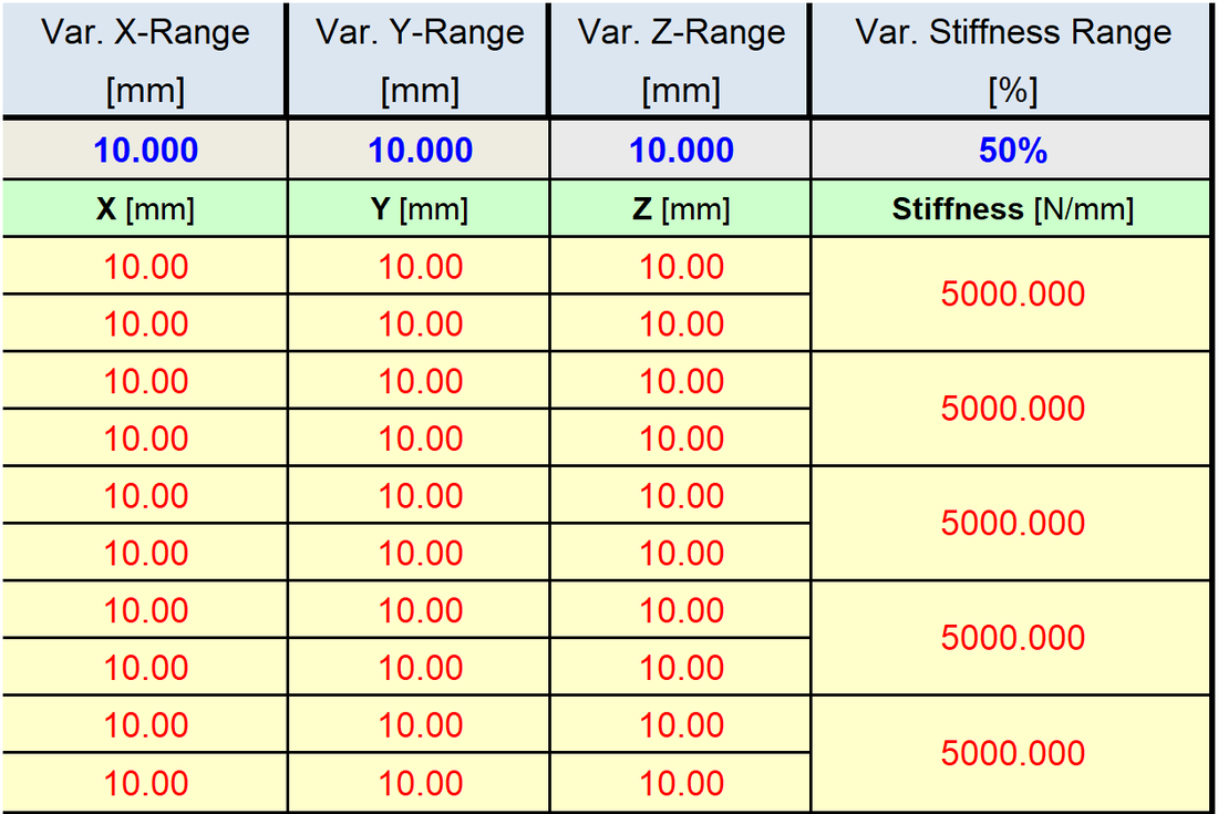
Additionally, the user can define the amount of change to the participating factor in the sensitivity study. |
|
The design space/operating range for the optimization process, which is entirely executed with the standard MS EXCEL SOLVER ADD-IN ® , can be fully customized to meet the specific requirements of the user.

The user can choose from three levels of "optimization involvement":
- Control and execute each step of the optimization process manually.
- Partially control the process.
- Execute quasi fully automatic optimization loop(s).
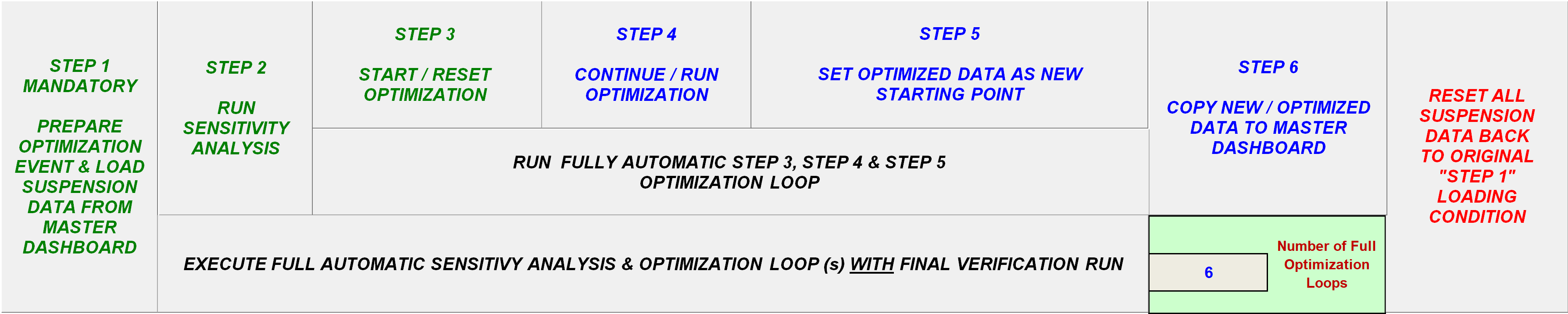
All three Levels are displayed in the Flow Chart below as Red, Amber & Green and as such indicating what should be the preferred User Selection.
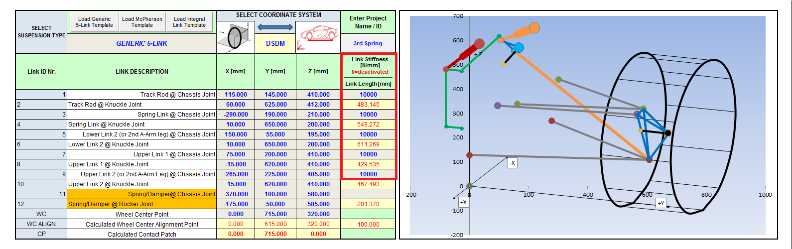
DYNATUNE SUSPENSION DESIGN MODULE - USER INTERFACE - SUSPENSION INPUT DATA
|
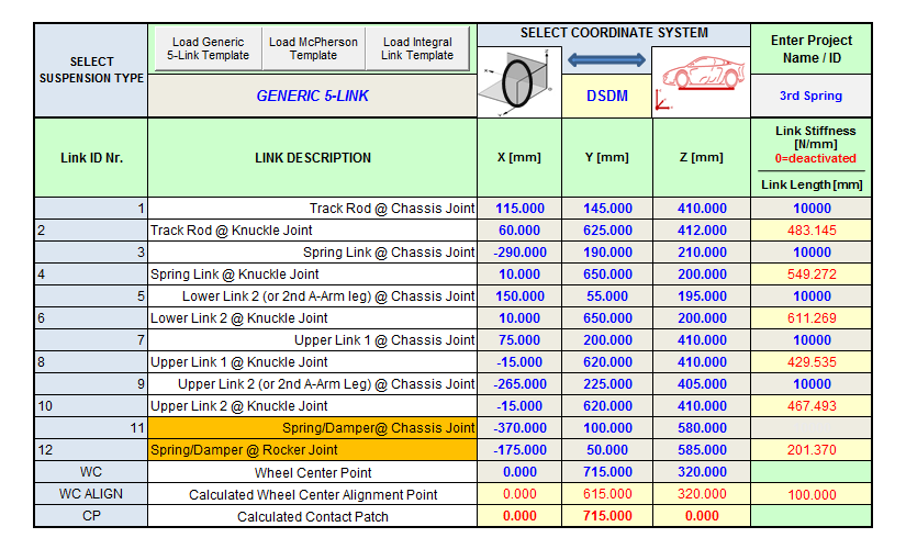
The primary input data for calculation includes the coordinates of the wheel, the 10 attachment points of the 5 links, and the 2 coordinates of the spring/damper unit. These coordinates can be entered in either the proprietary DYNATUNE-XL SDM Coordinate System (DSDM) or a typical OEM Coordinate System, with subsequent coordinate transformation into DSDM sign conventions.
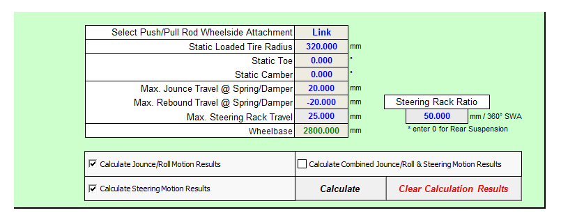
Additionally, specific setup and car data such as STATIC TOE, CAMBER, and STATIC LOADED RADIUS must be entered. In the case of a "steerable" suspension, the maximum spring/damper displacements in jounce/rebound travel or the maximum steering rack travel can also be specified. Calculation modes include:
From RELEASE 8.0 onward, steering motions and combined jounce and steering motions can be executed with the spring/damper unit (or push-rod) attached to the upright.
|
|
DYNATUNE SUSPENSION DESIGN MODULE - BASE GEOMETRIES
|
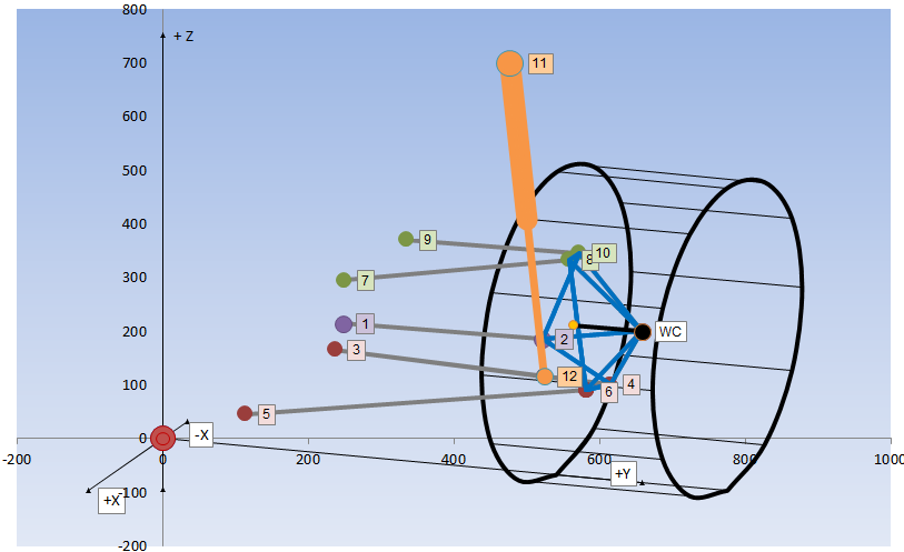
The DYNATUNE-XL SUSPENSION DESIGN MODULE is equipped with three standard base suspension templates, enabling the creation of 99% of the most commonly used suspension architectures in contemporary vehicles. The tool provides all the necessary resources to investigate the kinematics of these suspensions.
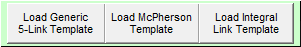
Optionally, users can display link identification labels. This feature is particularly helpful for novice users, aiding in a better understanding of the selected suspension architecture.
|
DYNATUNE SUSPENSION DESIGN MODULE - USER INTERFACE - Animation FEATURE
|
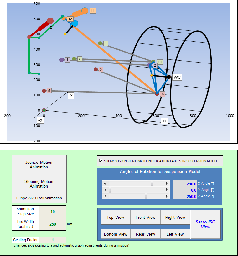
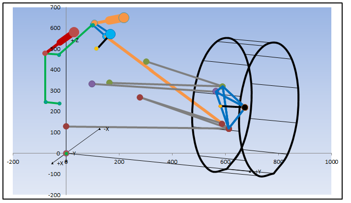
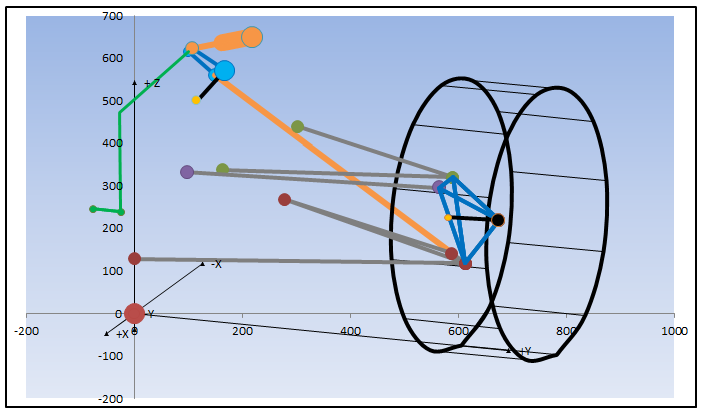
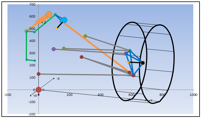
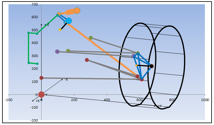
The DYNATUNE-XL SUSPENSION DESIGN MODULE includes a Corner Suspension View/Animation Window that allows users to check the model layout during the data input phase. It also enables the observation of the animation of jounce and steering motion, or if calculated, the combined motion as it would occur on the car. The animation can be executed with or without data labels activated.
For maximum user convenience, the View/Animation Window can be set to seven pre-set views or can be rotated around every reference axis by entering a custom rotation angle. The window can be scaled to zoom, and the animation "frame" rate can be set manually. This is especially convenient for suspension designs optimized for large wheel travels, typically seen on rally cars or heavy-duty off-highway vehicles. Tire width can be adapted solely for graphic rendering. |
|
DYNATUNE SUSPENSION DESIGN MODULE - USER INTERFACE - POST PROCESSING
TABULAR RESULTS:
|
As mentioned earlier, the post-processing in the DYNATUNE-XL SUSPENSION DESIGN MODULE relies entirely on applied vector algebra. This implies that all results are derived solely from the three-dimensional movement of the upright/knuckle. This approach allows for the correct calculation of all suspension parameters, even for complex suspensions with a virtual steering axis.
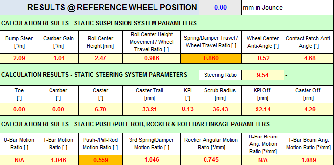
For quick reference and model verification, users can check the most important suspension and steering system parameters in a small table. This table can be manually updated for various wheel positions. |
In situations where specific rocker linkages are employed, the RESULTS output table includes crucial data and characteristics of the push-/pull-rod, rocker, and anti-roll bar linkage. This encompasses not only classical translational motion ratios for coil spring systems but also incorporates calculations for angular motion ratios and deflection angles. These additional metrics aid in designing systems based on torsion springs in the rocker axis.
The RESULTS Sheet provides a comprehensive array of characteristics, all presented as a function of wheel travel or steering angle.
The RESULTS Sheet provides a comprehensive array of characteristics, all presented as a function of wheel travel or steering angle.
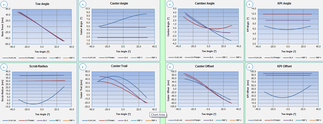
GRAPHIC RESULTS:
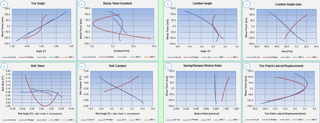
For in-depth analysis, a set of 28 pre-set graphs is available in the DYNATUNE-XL SUSPENSION DESIGN MODULE. These graphs can be conveniently enlarged to a custom set value and allow for the comparison of up to 5 variants simultaneously. The graphs are organized based on their typical use, either for Jounce/Roll Motion or Steering Motion results.
For in-depth analysis, a set of 28 pre-set graphs is available in the DYNATUNE-XL SUSPENSION DESIGN MODULE. These graphs can be conveniently enlarged to a custom set value and allow for the comparison of up to 5 variants simultaneously. The graphs are organized based on their typical use, either for Jounce/Roll Motion or Steering Motion results.
Jounce/Roll Motion Results: Steering Motion Results:
|
|
DYNATUNE SUSPENSION DESIGN MODULE - USER INTERFACE - DATA MANAGEMENT
|
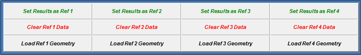
All calculation results are stored in a freely customizable RESULTS Sheet within the DYNATUNE-XL SUSPENSION DESIGN MODULE. This sheet encompasses more than 50 different data columns of suspension parameters and includes all the graphs available on the user interface for further custom post-processing.
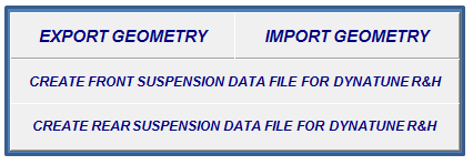
For convenience, up to 4 calculation results data sets can be stored, along with the input data, into 4 reference sheets for comparison and potential future reloading/recalculation. Additionally, users have the option to export the suspension model data set into an external MS EXCEL ® file. This facilitates effective data management, providing a convenient way to transfer input data between different licenses of DYNATUNE-XL SDM or create a specialized data set for importing suspension data into DYNATUNE-XL R&H. |
|
DYNATUNE SUSPENSION DESIGN MODULE - RACE GEOMETRIES

|
In the "RACE" and "EXPERT" versions of the DYNATUNE-XL SUSPENSION DESIGN MODULE, a racing car focused Push-/Pull-Rod Rocker/Linkage System has been superimposed on the standard suspension architectures.
Users can choose whether these rocker systems include an anti-roll bar linkage or not. Moreover, the anti-roll bar linkage can be configured to be either a U-Bar or T-Bar configuration. 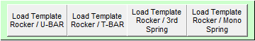
|
DYNATUNE SUSPENSION DESIGN MODULE - USER INTERFACE - RACE SUSPENSION INPUT DATA
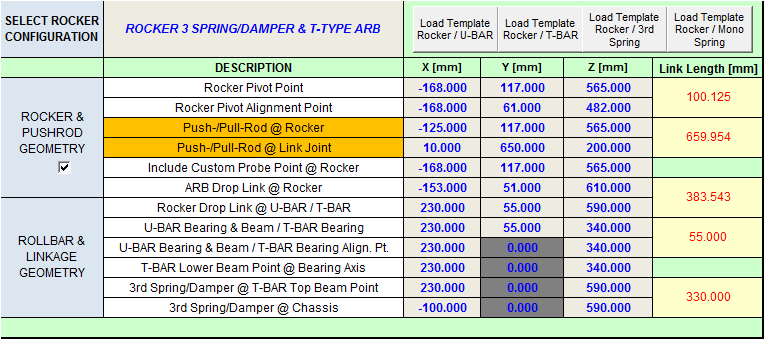
|
The primary input data for the push-/pull-rod, rocker, and anti-roll bar linkage includes the coordinates of the various attachment points. Users can input these coordinates in either the proprietary DYNATUNE-XL SUSPENSION DESIGN MODULE DSDM Coordinate System or a typical OEM Coordinate System, with subsequent coordinate transformation into DSDM sign conventions.
The input table dynamically adjusts based on the selected rocker configuration template. |
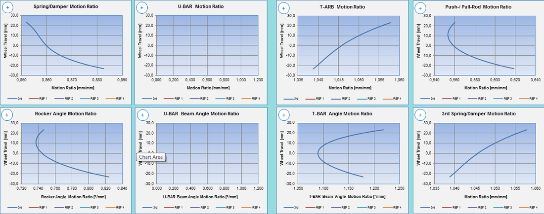
GRAPHIC RESULTS:
For a detailed analysis of the Rocker Linkage System, a set of 12 additional pre-set graphs is available in the DYNATUNE-XL SUSPENSION DESIGN MODULE. These graphs can be conveniently enlarged to a custom set value and enable the comparison of up to 5 variants simultaneously. The graphs are organized based on their typical use in Jounce/Roll Motion.
For a detailed analysis of the Rocker Linkage System, a set of 12 additional pre-set graphs is available in the DYNATUNE-XL SUSPENSION DESIGN MODULE. These graphs can be conveniently enlarged to a custom set value and enable the comparison of up to 5 variants simultaneously. The graphs are organized based on their typical use in Jounce/Roll Motion.
DYNATUNE SUSPENSION DESIGN MODULE - SUSPENSION COMPLIANCE
Tje key feature of the DYNATUNE-XL "EXPERT" SUSPENSION DESIGN MODULE is the unique capability of incorporating link stiffness into the geometry. This feature enables the investigation of compliant suspension characteristics. Users can activate or deactivate link compliance by entering appropriate values in the corresponding input cells or setting the numbers to 0. This functionality allows for a detailed analysis of the influence of each link on overall suspension performance, serving as an excellent upfront design tool before resorting to complex and costly multi-body-system analysis tools.
|
The results for all compliance effects are displayed in the table below. Users can enter a value for pneumatic trail to consider the effect of tire aligning torque. Additionally, when using a McPherson strut suspension, the bending of a damper strut can be optionally included.
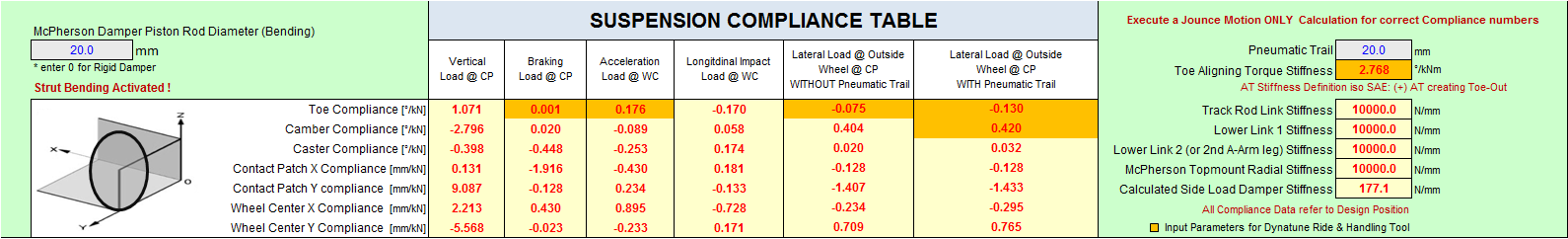
When entering link stiffness values, this table will be automatically calculated and presented for all load applications that can apply the wheel's typical geometry compliance gradients. In effect, the table summarizes, for the most commonly used suspension parameters, how much each parameter changes per kN of applied load.
|
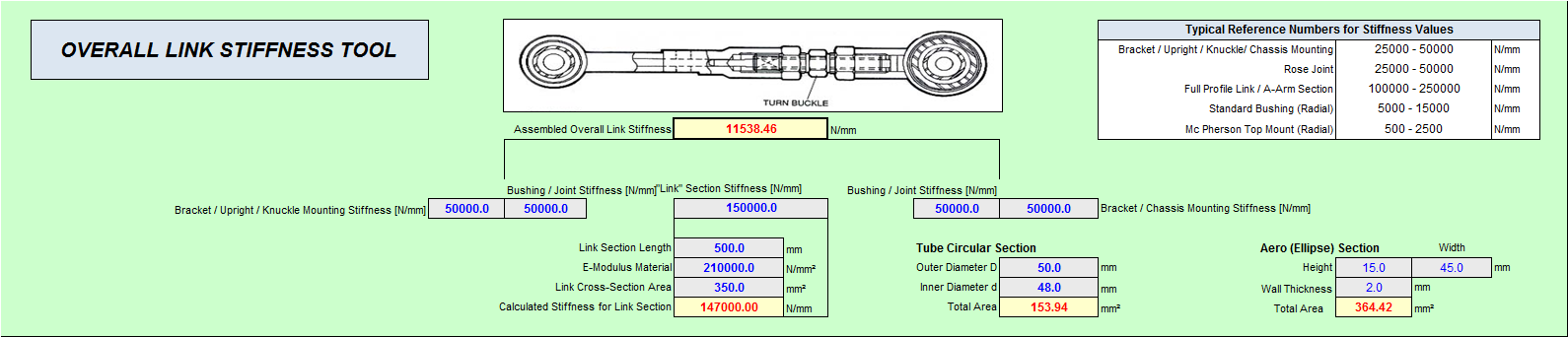
The link stiffness value is a "lumped number" composed of various local stiffness contributors that need to be consolidated into a single value. The tool displayed below is used to add/break down the most important stiffness contributors in the overall link assembly system. By entering measured numbers or relying on historical reference numbers, a good estimate for the total link stiffness can be calculated. Since all local stiffness contributors are added as "springs in series," the weakest component dominantly defines the final overall stiffness number.
|
DYNATUNE SUSPENSION DESIGN MODULE - LOADCASE ANALYSIS
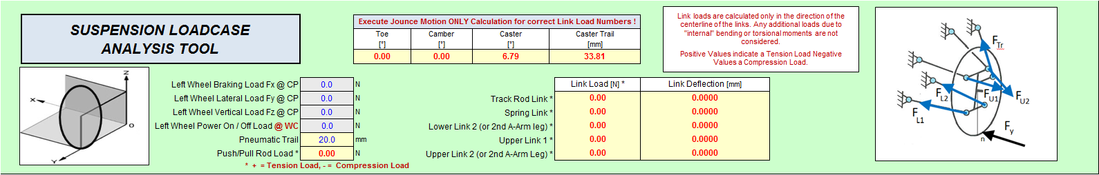
In addition to the unique Compliance Table, the SDM "EXPERT" Version also offers a SUSPENSION LOADCASE ANALYSIS TOOL, which allows entering specific loads at the contact patch/wheel center and calculating:
- The corresponding loads in each suspension link
- Toe, Camber & Caster for the applied wheel loads
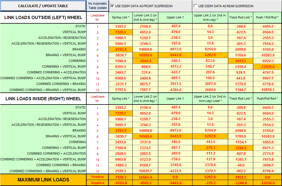
Lastly, the SDM "EXPERT" Version features from RELEASE 8.0 onward a major update to the VEHICLE LOADCASE GENERATION TOOL. This tool allows the creation of a reference table for approximate Suspension Corner Loads based on imposed vehicle accelerations in X, Y, Z direction, and aerodynamic loading. A basic "R&H-Type" Vehicle Model enables the creation of Vehicle Corner Loads, which are then transformed into Suspension Link Loads in a secondary step. Dynamic Load Factors can also be considered.
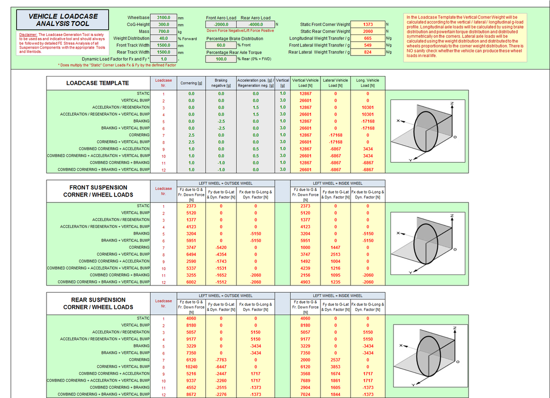
For ultimate convenience, an automatic Link Load Table Generator is included. By selecting the Vehicle Loadcases, one can create a table of Link Loads for either a Front Suspension or a Rear Suspension for all of the above defined Vehicle Loadcases.