DYNATUNE-XL SUSPENSION DESIGN MODULE - Modeling APPROACH
The DYNATUNE-XL SUSPENSION DESIGN MODULE is a tool that is completely based on vector algebraic equations, which are used to determine the generic 6 DOF (degrees of freedom) motion equations (3 translations, 3 rotations) of a "free-floating object in space." This knowledge can be applied directly to a Suspension Upright/Knuckle, which is held by several suspension links. By using only 5 of the 6 mentioned links and transforming the 6th link into a "spring," the free-floating movement of the Upright/Knuckle is reduced to just 1 translational degree of freedom: vertical wheel travel. All other movements are restricted by the links.
DYNATUNE-XL SUSPENSION DESIGN MODULE - UNLIMITED DESIGN POSSIBILITIES
The vector algebraic approach allows for a highly flexible method of suspension modeling. The generic equations, based on a 6x6 matrix covering full 3-dimensional movement, enable the modeling of nearly any suspension by combining and rearranging links. The same principle is applied to the Rocker Linkage in the for Racing Applications.
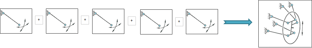
By combining the end of two links one can create A-Arms:
By combining the end of two links one can create A-Arms:
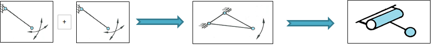
By combining 3 or more Links one can create H-Arms and so on:

DYNATUNE SUSPENSION DESIGN MODULE comes with 3 "Pre-Set" Base Suspensions Configurations that allow to create over 99% of all existing independent suspension types:
- Generic 5 Link: This configuration permits to create most of the existing independent suspensions, that are NOT characterized by a McPherson type Strut. By combining two, three or more links, one can create trailing arm suspensions (3 - 5 combined links), double wishbone suspension (max 4 combined links) and various types of multi-link suspensions (max 2 combined links).
- McPherson Strut: This configuration is a "particular" configuration of the Generic 5 Link Suspension where two of the "upper" links combine into an "infinitely" long upper wishbone creating in that manner the equivalent of a slider joint which is typical for any (McPherson) Strut Suspension.
- Integral Link: The 2 above configurations assume that all links are attached on either chassis side or upright side. An Integral Link Suspension however, is characterized by the fact that ONE link is NOT attached to the chassis but to another link, causing a very particular configuration of the GENERIC 5 LINK concept (BMW 5-Series).
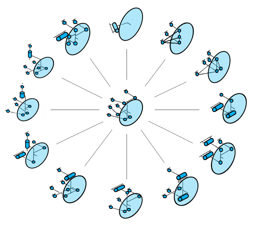
DYNATUNE-xL SUSPENSION DESIGN MODULE - SUSPENSION ARCHITECTURE LIBRARY
The GENERIC approach of the calculation algorithm permits creating a large database of Suspension Configurations from simple Trailing Arm configurations to full blown 5 Link Multi-Link Suspensions.
The picture below does show the Suspension Clock, a selection of possibly to be created Suspension Types:
|
Running Clockwise starting at 12 o'clock:
Center: Generic 5 Link Multi-Link Suspension |
DYNATUNE-XL SUSPENSION DESIGN MODULE - COMPLIANCE & LOAD-CASE Modeling
|
In the "EXPERT" Version of DYNATUNE-XL SDM, the unique feature is the ability to incorporate COMPLIANCE (Stiffness) into the Suspension Linkage System. Utilizing vector algebraic matrix operations, it becomes possible to extract the correlation between the axial displacement (i.e., in the direction of the link orientation) of each link and its effect on the wheel position.
For example, consider calculating the Contact Patch Lateral Displacement when moving the Track-Rod Link along its center line, similar to a steering movement. Once this relationship (a "ratio") is determined between these two displacements, the two forces (action and reaction) acting in the direction of these movements are proportional to the same ratio. Consequently, for an Fy (working in Lateral Contact Patch Displacement direction), the total Link Load on the Track-Rod Centerline can be directly calculated. Expanding this concept to all five links allows for the calculation of ALL the loads that act on the centerline of the links when loads are applied at the wheel for any Suspension Linkage Configuration. |

|
Once the loads on each link are known, the next step involves adding a "Link Stiffness" to determine the elastic deformation of each link. This results in the links becoming either "longer" or "shorter," depending on whether a compression or tension load is acting on the link. Changing the link lengths will lead to geometric (kinematic) changes, and by iterating this process over all five links, the "Compliant" Suspension Geometry Position can be determined for that particular load condition.
The Link Stiffness in real life is a lumped stiffness parameter consisting of three key local area stiffness values. These values must be added as "Springs in Series" to create a single number. The key local stiffness areas include:
CHASSIS / SUB-FRAME ATTACHMENT:
Chassis / Sub-frame attachment point stiffness (steel, titanium, aluminum or carbon fiber)
LINK ITSELF:
Bushing or Rose Joint stiffness on either side & Link Stiffness in between the "connection" points (steel, titanium, aluminum or carbon fiber)
UPRIGHT / KNUCKLE ATTACHMENT:
Knuckle / Upright attachment point stiffness (steel, titanium, aluminum or carbon fiber)
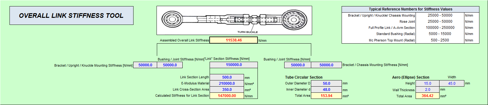
The above shown tool has been developed and incorporated in the software to calculate / estimate the overall "lumped" Link Stiffness.
NOTE-1: THE INTRODUCED LINK STIFFNESS DOES NOT AFFECT THE PURE KINEMATIC ANALYSIS OF THE SUSPENSION GEOMETRY. ALL COMPLIANCE CHARACTERISTICS ARE CALCULATED "ON TOP" OF THE KINEMATIC RESULTS._
NOTE-2: SINCE THE SUSPENSION TOOL IS BASED ON (TENSION & COMPRESSION) LINKS ANY PARTICULAR BENDING MOMENTS ON THE LINKS ARE NOT BEING CONSIDERED.
NOTE-3: COMPLEX BUSHINGS WITH SIGNIFICANT DIFFERENCES IN AXIAL & RADIAL RATE(S) OR NON-LINEAR STIFFNESS PROGRESSION CURVES CANNOT BE ACCURATELY MODELED WITH THE LINEAR LINK-STIFFNESS CONCEPT AND WILL RESULT IN LESS ACCURATE RESULTS.
DYNATUNE-XL SUSPENSION DESIGN MODULE - STRUT BENDING Modeling
|
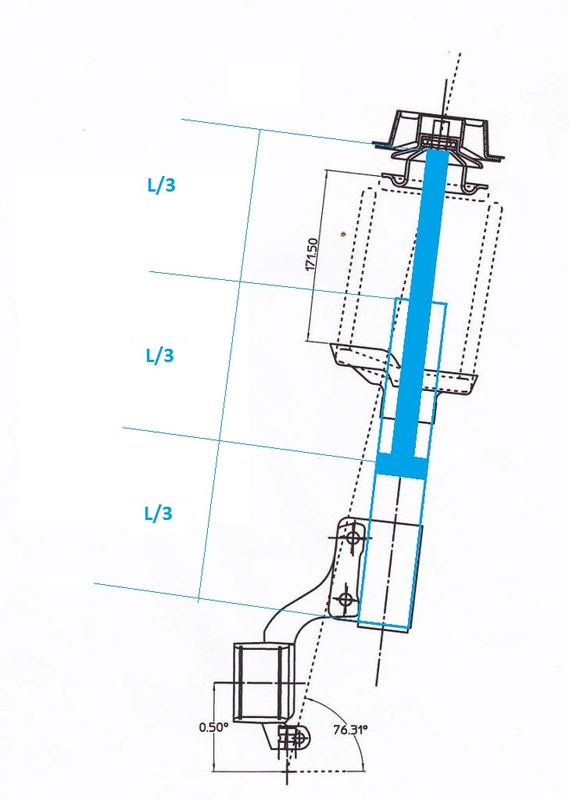
In order to investigate compliant suspension behavior on a Strut Suspension, it is fundamental to implement Strut Bending. The Damper Piston Rod deforms under Vertical, Lateral and Longitudinal wheel loads and causes thus (significant) changes in the kinematic suspension parameters.
In the DYNATUNE-XL SUSPENSION DESIGN MODULE "EXPERT" Version the Strut Bending Model consists of an Elementary Beam Element representing the Piston Rod of the Damper with the indicated (automatically calculated) geometric dimensions. The Strut Model comes with a Specific Tool in the Module permitting the user to enter additional needed data like Damper Rod Diameter. |