DYNATUNE-XL DRIVE-LINE DESIGN MODULE (DDM)
|
The DYNATUNE-XL DRIVE-LINE DESIGN MODULE has been developed to optimize the best match between the Drive-Train and Power Unit Characteristics in order to optimize acceleration performance and/or Drive-Line Efficiency considering the dynamic effects of Rotational Inertia's. To achieve this, the Module does offer the capability to provide up to 8 Gearbox Ratios, a Differential Reduction and typical Rotational Inertias for Power Unit Rotating Parts, Drive-Line Rotating Parts and Wheels & Brake Discs.
From RELEASE 8.0 onward of the Drive-Line Module, one can either provide a classical Internal Combustion Engine (ICE) Torque Map - either directly measured on an Engine Dyno or to be generated out of measured Power at the Wheel Data - as a function of RPM or a Typical Torque Speed Curve from a Motor Generator Unit (MGU). |
Drive-line input data
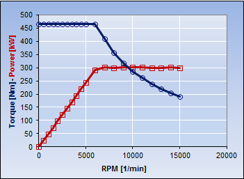
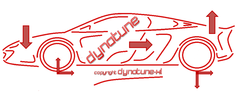
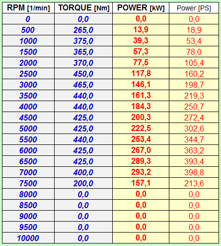
Users can enter the Internal Combustion Engine (ICE) or Motor Generator Unit (MGU) RPM/Torque map of the power unit in the Drive-Line Module. This can be done with up to 21 data points, allowing for a precise reproduction of the engine data. The input can cover steps of 500 RPM from 0 RPM up to 10,000 RPM, increments of 1000 RPM from 0 to 20,000 RPM, or any other desired step size.
|
In RELEASE 8.0, the Gearbox allows users to specify from 1 to up to 8 gear ratios. This feature enables the simulation of the most commonly used gearboxes for Internal Combustion Engine (ICE) or Electric Vehicle (EV) Powertrain applications in automotive or motorcylcle engineering applications.
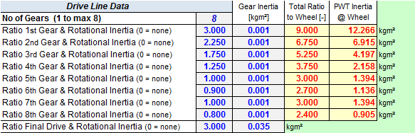
In RELEASE 8.0 all Drive-Line Rotational Inertia's are considered.
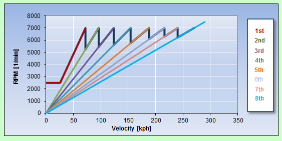
The Drive-Line Module allows users to input essential vehicle data, including Vehicle Mass, Weight Distribution, Aerodynamic Data, and Tire Grip. A Gear Ratio/RPM-Velocity chart provides quick access to key information about the drive-line layout.
Additionally, users can input drive-line control data, specifying shifting times in increments of 0.01 seconds, and adjust the powertrain architecture from Front-Wheel Drive (FWD) to All-Wheel Drive (AWD) to Rear-Wheel Drive (RWD) by indicating the percentage of torque transferred to the rear wheels. |
|
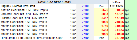
In addition to the specified Shift Time for each gear, users can set Up-Shift RPM and the Max. Rev limit of the Power Unit. RPM drops at gear shifts are automatically calculated, providing numerical data for the Ratio/RPM Velocity Chart.
The clutch Stall RPM parameter allows for the exploration and identification of the optimal Internal Combustion Engine (ICE) RPM for performance starts. |
|
VEHICLE Data
|
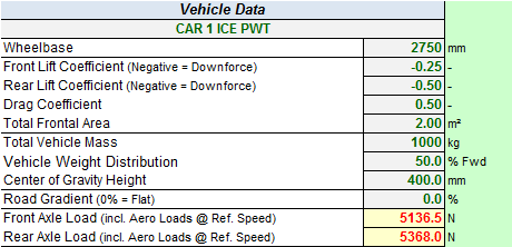
The most critical vehicle data includes Vehicle Mass, Weight Distribution, Center of Gravity Height, and Wheelbase, as these parameters determine longitudinal load transfer and wheel loads during acceleration. Additionally, the DYNATUNE_XL DDM takes into account Aerodynamic Data, Tire Rolling Resistance, and Road Gradient (included for Hill Climb Racing), as these factors play a crucial role in limiting acceleration.
It's worth noting that DYNATUNE-XL DDM can effectively simulate high downforce vehicles, considering the impact of particularly high (negative) Lift and Drag Coefficients on acceleration performance. Axle loads can be generated for any desired speed if needed. |
RESULTS
|
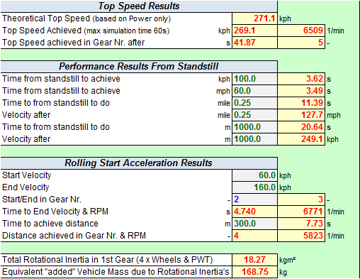
NUMERICAL RESULTS provide key performance metrics commonly used in Performance Tests related to both time and distance. Users have the flexibility to vary all points of interest within reasonable limits, ensuring that the maximum (simulation) time required does not exceed 1 minute.
As a guide, the tool automatically calculates the theoretical maximum speed achievable based solely on the available power. This aids in identifying any potential issues with selected gear ratios or the final drive. Additionally, the tool calculates the maximum possible accelerations for FWD or RWD and the optimal AWD configuration (with corresponding Front to Rear Torque Distribution) to achieve maximum acceleration at a given speed. In RELEASE 8.0, DYNATUNE-XL DDM documents the effect of Rotational Inertia in the Performance Figure Table. |
|
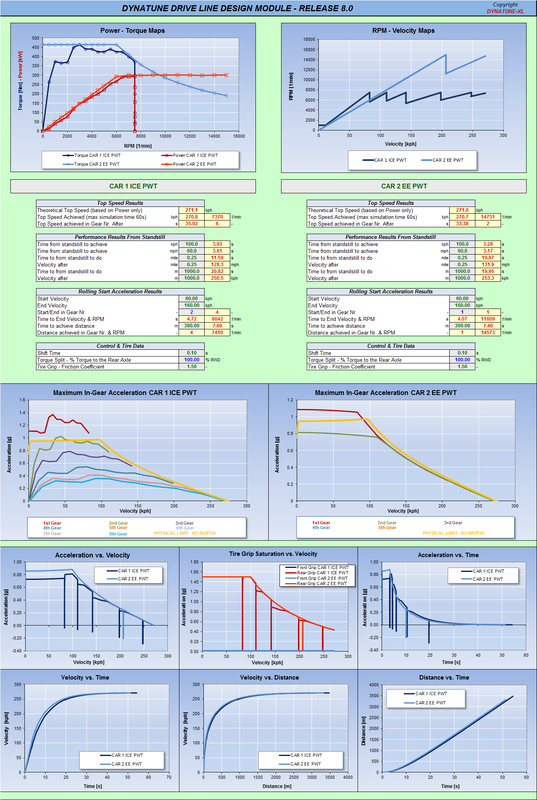
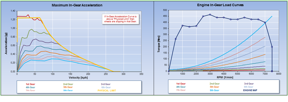
GRAPHICAL RESULTS comprise various graphs, including several Time History Plots and two key "major" graphs:
- Maximum Acceleration vs. Velocity Graph: This graph plots the maximum acceleration of the vehicle against its velocity for each available gear. It considers the limits of tire grip and the combined effects of Rolling Resistance, Aerodynamic Resistance, and Road Gradient. This is particularly crucial for vehicles involved in hill climbing.
- Limiting Factors Graph: The second graph depicts the sum of all limiting factors, including Rolling Resistance, Aerodynamic Resistance, and Road Gradient, into the Engine Torque Map. This provides immediate insight into the optimality of the selected gear ratios.
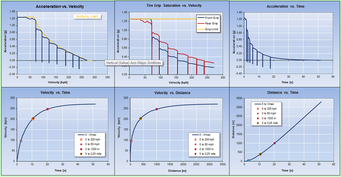
The additional 6 plots offer comprehensive visual information to finalize the analysis of Vehicle Acceleration, Velocity, and Distance. Given the significance of Acceleration vs. Velocity as a key metric, this information can be directly compared with the Saturation of the Tire Grip. This aids in identifying instances of wheel spin or cessation and determining the optimal stall clutch RPM for achieving optimal traction in 1st Gear.
The workbook also includes a COMPARISON Sheet that lists all key parameters and graphs for two vehicles, facilitating an easy side-by-side comparison of variants. Refer to the DDM PDF file for more details on this.