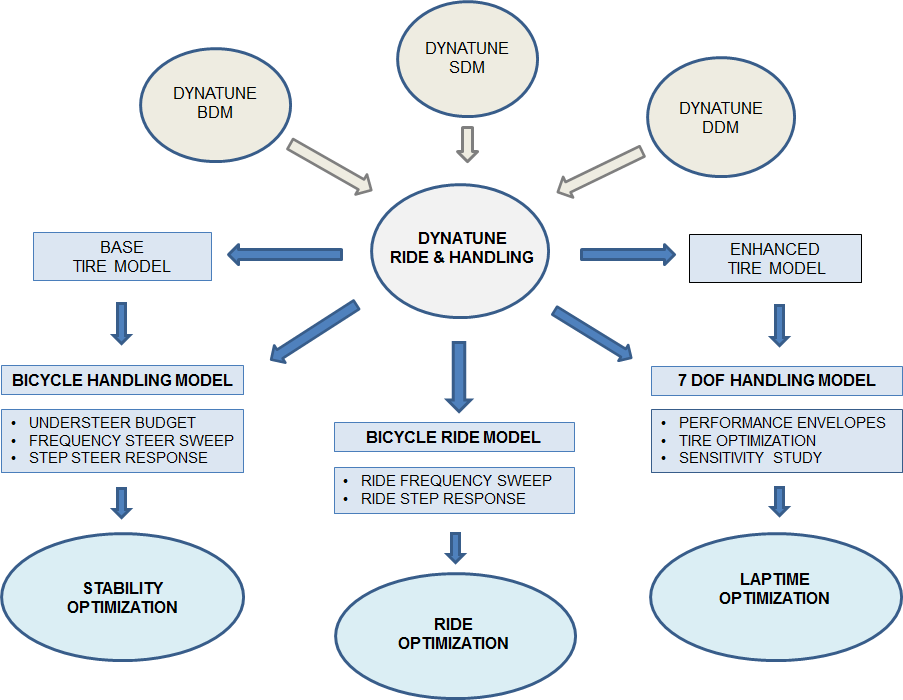
DYNATUNE-XL RIDE & HANDLING MODUE - MODELING APPROACH
Throughout its years of development, the architecture of the DYNATUNE-XL RIDE & HANDLING MODULE has been shaped by some key features and the inclusion of two tire models:
These 3 Key-Features and 2 Tire Models have governed the Architecture of the Tool until now:
- Yaw Frequency Response Function Calculation:
- Starting Point: The tool originated as a Lotus 123 sheet designed to calculate the Yaw Frequency Response Function using the equations of a Bicycle Model.
- Evolution: The initial Tire model comprised only Front & Rear Axle Cornering Stiffness, evolving into the BASE TIRE MODEL.
- 7-DOF-Model Addition:
- Evolution: In RELEASE 7.0, a 7-DOF-Vehicle Dynamics Model was introduced to calculate more specific vehicle data, requiring a more sophisticated Tire Model, which led to the development of the ENHANCED TIRE MODEL.
- Evolution: In RELEASE 7.0, a 7-DOF-Vehicle Dynamics Model was introduced to calculate more specific vehicle data, requiring a more sophisticated Tire Model, which led to the development of the ENHANCED TIRE MODEL.
- Incorporation of Basic Ride Model:
- Evolution: A basic Ride Model was incorporated to create a comprehensive "One for All" tool for the fundamental setup of a vehicle's Ride & Handling.
- Evolution: A basic Ride Model was incorporated to create a comprehensive "One for All" tool for the fundamental setup of a vehicle's Ride & Handling.
These 3 Key-Features and 2 Tire Models have governed the Architecture of the Tool until now:
BASE Vehicle Modelling Approach Bicycle MODEL
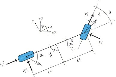
The development of DYNATUNE-XL RIDE & HANDLING MODULE initially centered around the standard equations of a linear bicycle model.
The linear bicycle model is a well-established concept in automotive engineering literature and is widely used, especially in electronic stability control (ESP) systems, where it accurately estimates vehicle conditions, including extreme scenarios. While the traditional limitations of a Bicycle Model involve being a Single-Track Model without accounting for Vehicle Roll effects, the approach in the DYNATUNE-XL R&H MODULE overcomes these limitations. Additional detailed chassis calculations are incorporated, and Elasto-Kinematic Suspension & Tire Characteristics are integrated into a unified Front and Rear AXLE cornering stiffness, following the principles introduced by BUNDORF. This enhanced approach allows the Bicycle Model to accurately calculate critical metrics such as Understeer Budget, Step Steer Response, and Frequency Steer Response across various load conditions, extending into the non-linear range of the tire. |
ADVANCED VEHICLE MODELING APPROACH
|
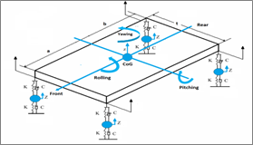
In the DYNATUNE-XL R&H 7-DOF model, all instantaneous contact patch loads in the X-Y-Z directions, resulting from aerodynamic loads, traction/braking, and lateral acceleration, are calculated for the specified vehicle condition.
These contact patch loads are then used to determine various parameters, including wheel deflections, kinematic and elasto-kinematic wheel movements, ride-height changes, and the instantaneous center of gravity height. All relevant parameters and calculation results from the 7-DOF vehicle model are utilized, when necessary, to update the boundary conditions of the linear bicycle model.
The 7-DOF model allows for the extraction of resulting axle cornering stiffness for any condition of lateral acceleration. Transferring this information to the bicycle model enables the evaluation of understeer budget and transient stability at the given operating condition. This approach extends the usability of the bicycle model even beyond the linear range of the tire.
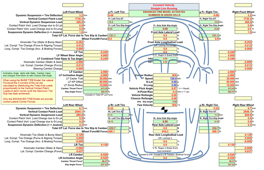
In RELEASE 8.1 one can find on the Car-Center-line all the results for the Additionally introduced new Power-Train Features. The new Steering System Parameters can be found on the Left 7 Right Front Wheel Section.
These contact patch loads are then used to determine various parameters, including wheel deflections, kinematic and elasto-kinematic wheel movements, ride-height changes, and the instantaneous center of gravity height. All relevant parameters and calculation results from the 7-DOF vehicle model are utilized, when necessary, to update the boundary conditions of the linear bicycle model.
The 7-DOF model allows for the extraction of resulting axle cornering stiffness for any condition of lateral acceleration. Transferring this information to the bicycle model enables the evaluation of understeer budget and transient stability at the given operating condition. This approach extends the usability of the bicycle model even beyond the linear range of the tire.
In RELEASE 8.1 one can find on the Car-Center-line all the results for the Additionally introduced new Power-Train Features. The new Steering System Parameters can be found on the Left 7 Right Front Wheel Section.
VEHICLE MODELING APPROACH - TIRE MODELS
1 - BASE TIRE MODEL
Correct tire data is essential for accurate vehicle behavior simulation. In DYNATUNE-XL R&H, linear vehicle behavior is calculated using a bicycle model based on front and rear cornering stiffness. This approach simplifies tire data management, focusing on the most important principal tire-parameter-identifiers.
The key tire parameters considered in the "BASE TIRE MODEL" include:
- Grip Level (Friction Coefficient µ) [-]
These parameters are fundamental for capturing the tire's influence on the vehicle's handling characteristics. The simplified model allows for efficient analysis while retaining accuracy in linear vehicle dynamics.
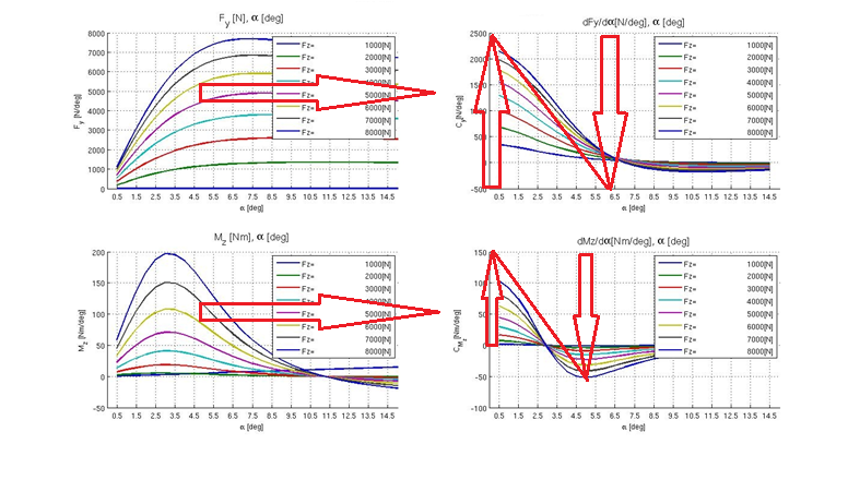
The tire characteristics, including "Lateral Force" and "Aligning Moment," exhibit non-linear behavior (quadratic/parabolic function) over slip angle, as shown in the left graphs above. However, their derivatives, "Cornering Stiffness" and "Aligning Torque Stiffness," demonstrate nearly linear behavior in the operating range, as depicted in the right graphs. The DYNATUNE-XL R&H "BASE TIRE MODEL" assumes (partially) linear behavior for these parameters, enabling a robust approach to high g-levels.
In practical terms, the Cornering Stiffness (or Aligning Torque Stiffness) increases with increasing vertical load (arrow-up) and decreases with increasing slip angle (increasing lateral load) close to 0 at the maximum grip level (arrow-down), as indicated by the red arrows in the right graphs. The operating range is identified with the diagonal line. For each axle, a Resulting Axle Cornering Stiffness is calculated based on the load transfer data from the 7-DOF Model. This results in correct Front and Rear Axle Cornering Stiffness for a particular lateral g-level.
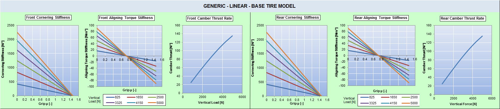
The Front and Rear main Tire Parameters are defined at a Reference Load Condition and are somewhat scalable with a parameter governing tire sensitivity to vertical load changes. By using a Reference Load and a Load Sensitivity Parameter, the DYNATUNE-XL R&H "BASE TIRE MODEL" can be easily adjusted to reflect correct tire behavior for any specific load condition of the vehicle.
These parameters are fundamental for capturing the tire's influence on the vehicle's handling characteristics. The simplified model allows for efficient analysis while retaining accuracy in linear vehicle dynamics.
The key tire parameters considered in the "BASE TIRE MODEL" include:
- Grip Level (Friction Coefficient µ) [-]
- - Cornering Stiffness [N/°]
- - Camber Thrust [N/°]
- - Aligning Torque Stiffness [Nm/°]
These parameters are fundamental for capturing the tire's influence on the vehicle's handling characteristics. The simplified model allows for efficient analysis while retaining accuracy in linear vehicle dynamics.
The tire characteristics, including "Lateral Force" and "Aligning Moment," exhibit non-linear behavior (quadratic/parabolic function) over slip angle, as shown in the left graphs above. However, their derivatives, "Cornering Stiffness" and "Aligning Torque Stiffness," demonstrate nearly linear behavior in the operating range, as depicted in the right graphs. The DYNATUNE-XL R&H "BASE TIRE MODEL" assumes (partially) linear behavior for these parameters, enabling a robust approach to high g-levels.
In practical terms, the Cornering Stiffness (or Aligning Torque Stiffness) increases with increasing vertical load (arrow-up) and decreases with increasing slip angle (increasing lateral load) close to 0 at the maximum grip level (arrow-down), as indicated by the red arrows in the right graphs. The operating range is identified with the diagonal line. For each axle, a Resulting Axle Cornering Stiffness is calculated based on the load transfer data from the 7-DOF Model. This results in correct Front and Rear Axle Cornering Stiffness for a particular lateral g-level.
The Front and Rear main Tire Parameters are defined at a Reference Load Condition and are somewhat scalable with a parameter governing tire sensitivity to vertical load changes. By using a Reference Load and a Load Sensitivity Parameter, the DYNATUNE-XL R&H "BASE TIRE MODEL" can be easily adjusted to reflect correct tire behavior for any specific load condition of the vehicle.
These parameters are fundamental for capturing the tire's influence on the vehicle's handling characteristics. The simplified model allows for efficient analysis while retaining accuracy in linear vehicle dynamics.
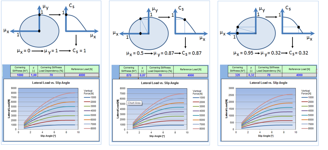
In the DYNATUNE-XL R&H MODULE, combined slip conditions, involving both lateral and longitudinal tire loads, are simulated using the Friction Circle Equations for Tire Friction Coefficient µ. The concept of the friction circle involves the interplay between lateral and longitudinal forces, and it's often represented graphically as a circle on a coordinate system.
Specifically, when there is "zero" longitudinal force (near the center of the friction circle), the tire's cornering stiffness is maximal. As the longitudinal force increases, the tire's cornering stiffness decreases. Similarly, the lateral friction coefficient µ is maximal when there is "zero" longitudinal load and minimal at the maximum traction/braking force.
This approach allows for an accurate simulation of tire behavior under various combined slip conditions, providing insights into the complex interactions between lateral and longitudinal forces on the tire's performance.
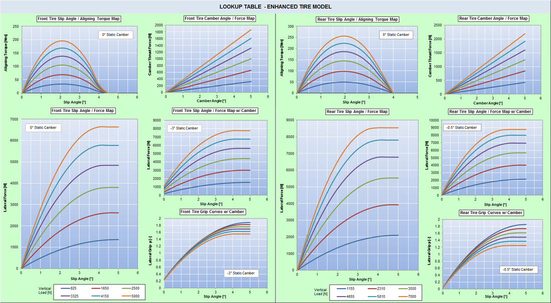
2 - ENHANCED TIRE MODEL
The "ENHANCED TIRE MODEL" in the DYNATUNE-XL R&H MODULE, introduced from RELEASE 7.0 onward, extends the capabilities of the "BASE TIRE MODEL" by transforming its parameters into a conventional NON-LINEAR TIRE MAP. This enhanced model represents lateral tire force as a function of tire slip angle and tire vertical load, allowing for more accurate simulations, especially at high lateral accelerations.
The specific TIRE DATA USER TOOL provides a visual representation of the tire data from the Enhanced Tire Model, making it easier for users to understand and analyze the non-linear behavior of the tire. The Enhanced Tire Model is particularly valuable for calculations based on the 7-DOF Vehicle Model, where accurate representation of tire behavior at high lateral accelerations is crucial.
It's worth noting that while the "ENHANCED TIRE MODEL" is used for non-linear calculations, the "BASE TIRE MODEL" continues to be employed for linear calculations and procedures based on the Bicycle Model. This dual-model approach allows for a balanced and accurate representation of tire behavior across a range of conditions.
|
In RELEASE 8.0 of the DYNATUNE-XL R&H MODULE, significant upgrades have been introduced to increase the flexibility and accuracy of the "ENHANCED TIRE MODEL".
Amongst various minor detail enhancements (as shown below), two major key tire performance enablers have been implemented (right). 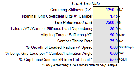
|
|
These enhancements in RELEASE 8.0 contribute to the improved realism and versatility of the ENHANCED TIRE MODEL within DYNATUNE-XL R&H MODULES. A typical Tire Data Map Representation is shown in the picture below:
NOTE:
- DYNATUNE DOES NOT USE TIRE RELAXATION-LENGTH PARAMETERS.
- DYNATUNE DOES NOT USE TIRE RELAXATION-LENGTH PARAMETERS.
VEHICLE MODELING APPROACH - POWER-TRAIN & BRAKE-SYSTEM
|
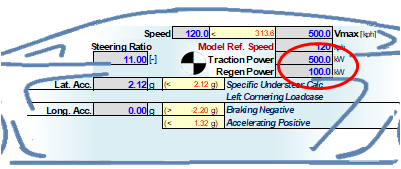
In the DYNATUNE-XL R&H MODULE, the powertrain is represented in a basic and elementary manner, where the user defines the power applied to the wheels. As of RELEASE 8.1, there is an additional capability to model braking power applied to the wheels.
This enhancement allows users to simulate various scenarios, such as regenerative braking or the effects of internal combustion engine (ICE) overrun in conjunction with Limited Slip Differentials. This provides a more comprehensive representation of the powertrain dynamics, especially in scenarios involving braking forces. |
|

|
In the DYNATUNE-XL R&H MODULE, the powertrain model operates by providing the (necessary) power to the wheels at all times, without explicitly considering factors such as gear ratios or differential gear reductions. This simulation approach will next to considering traction/tire limited accelerations from standstill also allow for the simulation of various types of power units, including both internal combustion engines (ICE) and electric vehicles (EV).
For a more detailed analysis of the driveline, including considerations of gear ratios and differential effects, users can utilize the DYNATUNE-XL DRIVE-LINE DESIGN MODULE. This module is designed to provide a more in-depth understanding of the drivetrain dynamics and is a valuable tool for comprehensive driveline analysis and design. |
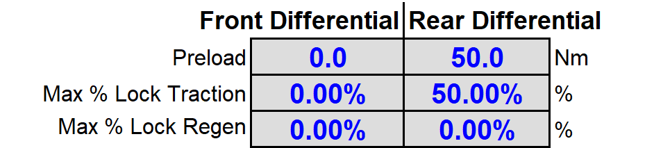
In DYNATUNE-XL R&H MODULE RELEASE 8.1, users have the option to incorporate Limited Slip Differentials into the simulation.
|
Limited Slip Differentials are characterized by parameters such as Preload and Locking Percentage. The Preload induces some initial locking effect, and the Locking Percentage indicates the amount of traction torque difference between the outside wheel and the inside wheel. This feature allows users to model and analyze the effects of Limited Slip Differentials, including scenarios involving overrun or regenerative braking.
|
|
In Real-Life conditions, when a vehicle is running straight (i.e. lateral acceleration G-Lat = 0), the presence of Differential Preload in a Limited Slip Differential will introduce an additional understeering component to the Linear Understeer Gradient. This effect is considered in the DYNATUNE-XL R&H MODULE and is reflected in the simulation results (see BUNDORF Table), taking into account the impact of Differential Preload on vehicle dynamics. It's important to note that the Differential Preload is treated as an "Internal Moment" in the simulation, and for simplification purposes, it doesn't explicitly contribute to additional longitudinal forces.
|
In simulation conditions where lateral acceleration (G-Lat) is not equal to zero (G-Lat <> 0) and longitudinal acceleration (G-Long) is also not equal to zero (G-Long <> 0), the Limited Slip Differential (LSD) will become active, provided it is activated in the simulation settings. The LSD will distribute the drive torque across the axle to the higher loaded (outside) wheel. This distribution will continue until the instantaneous grip level is reached, at which point the simulation will stop.
|
|
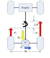
The induced difference between left and right longitudinal forces, resulting from the action of the LSD, will create an additional yaw moment around the Center of Gravity (CoG) of the vehicle. In the case of traction, this additional yaw moment will support the turning of the vehicle, leading to Oversteer. In the case of overruns or regenerative braking, it will reduce the turning of the vehicle, resulting in Understeer.
|
If no Limited Slip Differential (LSD) has been activated, the simulation will stop as soon as one wheel loses grip and starts spinning freely. The same principle applies to hydraulic braking, where the simulation will stop if one of the wheels locks up.
To investigate "Full" Torque Vectoring* in Braking and Traction conditions, similar to what can be seen in high-performance electric vehicles with four motors, one can activate these features in the simulation settings. When these features are turned on, longitudinal forces* will be distributed according to the grip levels at all wheels, resulting in higher overall vehicle performance.
* excluding "full opposite" Forces (i.e traction & braking) on one axle.

VEHICLE MODELING APPROACH - DYNAMIC RIDE Model

The DYNATUNE-XL R&H Dynamic Linear Ride Model, used for calculating Ride Step Input and Ride Frequency Response, consists of two independent vertical half-vehicle models. Each half-vehicle includes front and rear body components, springs, and linearized dampers. The front and rear unsprung masses are connected to both the front and rear bodies through suspension springs and dampers. The connection to the ground is represented by the tire vertical spring combined with a generic tire damping value, typically derived from critical tire damping percentages. All equations are solved using Laplace Transformations.
Generic calculations for natural bounce and pitch frequencies, with or without bounce and pitch centers, are performed by solving the differential equations of a simplified reduced-order model.
Generic calculations for natural bounce and pitch frequencies, with or without bounce and pitch centers, are performed by solving the differential equations of a simplified reduced-order model.